
Micro projector based on pure laser optics engine

An optical engine and projector technology, applied in optics, instruments, projection devices, etc., can solve the problems of increasing the size of the projector, low luminous flux, and high design difficulty, so as to solve the problem of heat dissipation, reduce the volume of the optical machine, and reduce the amount of light. Loss of effect

Inactive Publication Date: 2017-01-11
SICHUAN CHANGHONG ELECTRIC CO LTD
View PDF5 Cites 9 Cited by
  • Summary
  • Abstract
  • Description
  • Claims
  • Application Information

AI Technical Summary

Problems solved by technology

However, due to the low luminous efficiency of the LED light source itself, the luminous flux is low
In addition, a collimating lens group needs to be installed at the rear end of the LED light source, and the collimating lens used is generally an aspherical lens, which is difficult to design and expensive
The system uses two beam-splitting lenses, which leads to large loss of light efficiency and low utilization rate of light energy, resulting in the luminous flux of the LED micro-projector not meeting the needs of users.
The production process of this type of LED micro-projector light machine is relatively complicated, expensive, and takes up a lot of space. The optical path structure is not compact enough, which increases the volume of the entire projector.

Method used


Image

  • Micro projector based on pure laser optics engine
  • Micro projector based on pure laser optics engine
  • Micro projector based on pure laser optics engine

Examples


Embodiment 1

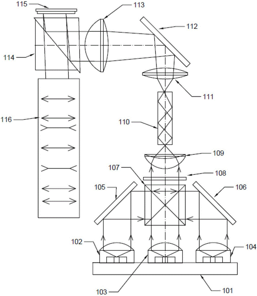
[0023] like figure 1As shown, a micro-projector based on a pure laser optical engine includes a projection lens A116 for projecting picture content to a projection screen. A103, blue laser light source A104, X prism A107, white light reflector A112, TIR prism A114, DLP light modulator A115 and projection lens A116, red laser light source A102, green laser light source A103, blue laser light source A104 from left to right Sequentially, an X prism A107 is correspondingly arranged above the heat dissipation copper plate A101 and directly above the green laser light source A103. The red laser light source A102, the green laser light source A103, and the blue laser light source A104 are all lasers. The red laser light source A102, the green laser light source A103, and the blue laser light source A104 simultaneously emit three parallel pure laser beams. The green laser light source A103 is used to transmit the emitted green laser beam parallel to the X prism A107, and the first fu...

Embodiment 2

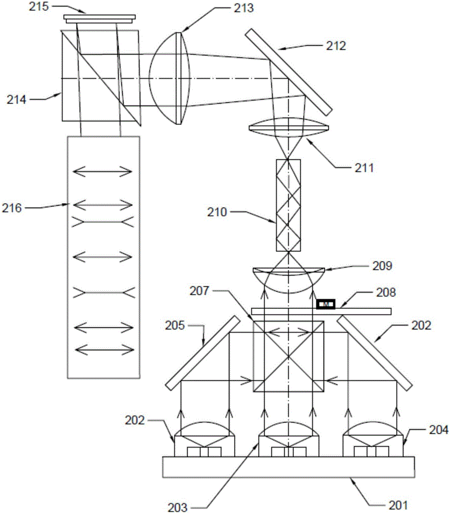
[0031] like figure 2 As shown, a micro-projector based on a pure laser optical engine includes a projection lens B216 for projecting screen content to a projection screen. The micro-projector in this embodiment also includes a heat dissipation copper plate B201, a red laser light source B202, a green laser light source B203, blue laser light source B204, X prism B207, white light reflector B212, TIR prism B214, DLP light modulator B215 and projection lens B216, red laser light source B202, green laser light source B203, blue laser light source B204 from left to right Sequentially, an X prism B207 is correspondingly arranged above the heat dissipation copper plate B201 and directly above the green laser light source B203. The red laser light source B202, the green laser light source B203, and the blue laser light source B204 are all lasers, and the red laser light source B202, the green laser light source B203, and the blue laser light source B204 simultaneously emit three par...

Embodiment 3

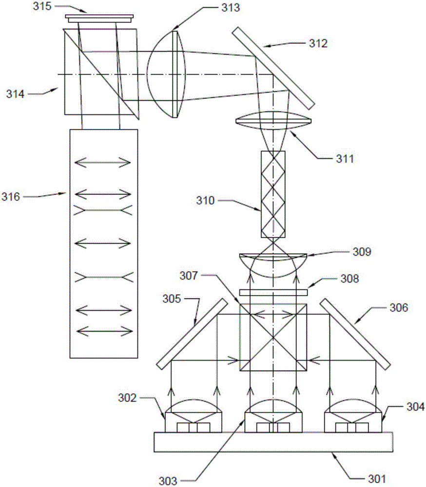
[0040] like image 3 As shown, a micro-projector based on a pure laser optical engine includes a projection lens C316 for projecting screen content to a projection screen. The micro-projector in this embodiment also includes a heat-dissipating copper plate C301, a red laser light source C302, a green laser light C303, blue laser source C304, X prism C307, white light reflector C312, TIR prism C314, DLP light modulator C315 and projection lens C316, red laser source C302, green laser source C303, blue laser source C304 from left to right Sequentially, an X prism C307 is correspondingly arranged above the heat dissipation copper plate C301 and directly above the green laser light source C303. The red laser light source C302, the green laser light source C303, and the blue laser light source C304 are all lasers. The red laser light source C302, the green laser light source C303, and the blue laser light source C304 simultaneously emit three parallel pure laser beams. The green l...


PUM


Abstract

The invention discloses a micro projector based on pure laser optics engine, comprising a projection lens A, a heat dissipation copper plate A, a red laser light source A, a green laser light source A, a blue laser light source A, an X prism A, a white light reflector, a TIR (Total Internal Reflection) prism, and a DLP (Digital Light Processing) light modulator A. With a compact structure, the micro projector is reduced in volume; the pure three-color lasers are adopted and light transfer efficiency reduction possibly occurring due to the small volume is prevented, thereby effectively reducing light energy loss. Beside a radiator is together used by three-color lasers, a heat dissipation problem of a light supply device is successfully solved and practicability of an optical engine module is increased in the micro projector. Moreover, the optical engine part of the pure laser micro projector is changed, the lens especially for the non-spherical lens is reduced in use, and the volume and the cost are reduced, so that the price of the projector is approximate to the mass consumption level and the micro project is more likely to have a considerable market.

Description

technical field [0001] The invention relates to the technical field of digital micro-projection display, in particular to a micro-projector based on a pure laser optical engine. Background technique [0002] Micro projectors are also called pocket projectors and portable projectors. The miniature projector makes the traditional huge projector compact, portable, miniaturized, entertaining, and practical, making projection technology closer to life and entertainment. Driven by the strong demand of the majority of users, the pico projector technology has developed rapidly in recent years. DLP, LCOS and other products have launched portable handheld pico projector products (PICO), or projector models built into handheld mobile devices such as mobile phones. Group. Compared with traditional LCD and LCOS projectors, DLP projection products are favored by consumers because of their greater advantages in lumen brightness, video image display and contrast. [0003] For the existin...

Claims


Application Information

Patent Timeline
Patent Type & Authority Applications(China)
IPC IPC(8): G03B21/20G03B21/16
CPCG03B21/2033G03B21/16G03B21/2013
Inventor 陈志洁何龙文玮
Owner SICHUAN CHANGHONG ELECTRIC CO LTD
Learn More