
Low-temperature denitrification catalyst based on carbonized MOFs (metal organic frameworks) and preparation method thereof

A low-temperature denitration and catalyst technology, applied in physical/chemical process catalysts, chemical instruments and methods, organic compound/hydride/coordination complex catalysts, etc. Point reduction and other problems, to achieve the effect of easy operation, increased specific surface area, and favorable diffusion

Active Publication Date: 2017-01-25
SOUTH CHINA UNIV OF TECH
View PDF8 Cites 17 Cited by
  • Summary
  • Abstract
  • Description
  • Claims
  • Application Information

AI Technical Summary

Problems solved by technology

[0003] The problem that low-temperature SCR catalysts are currently facing is: some catalysts with good low-temperature denitrification activity, once there is SO in the flue gas 2 , its denitrification activity will drop sharply and lead to poisoning and deactivation of the denitrification catalyst. Therefore, it is necessary to improve the anti-SO 2 Performance is the key issue for its practical application
Second, irreversible poisoning, namely SO 2 It directly reacts with the metal ions of the active center, so that the metal atoms of the active center are sulfated and lose their catalytic activity. Because these sulfates have a high decomposition temperature and are not easy to decompose, they cover the surface of the catalyst and block the pores of the catalyst, resulting in the reduction of active sites and irreversible formula inactivation

Method used


Image

  • Low-temperature denitrification catalyst based on carbonized MOFs (metal organic frameworks) and preparation method thereof
  • Low-temperature denitrification catalyst based on carbonized MOFs (metal organic frameworks) and preparation method thereof
  • Low-temperature denitrification catalyst based on carbonized MOFs (metal organic frameworks) and preparation method thereof

Examples


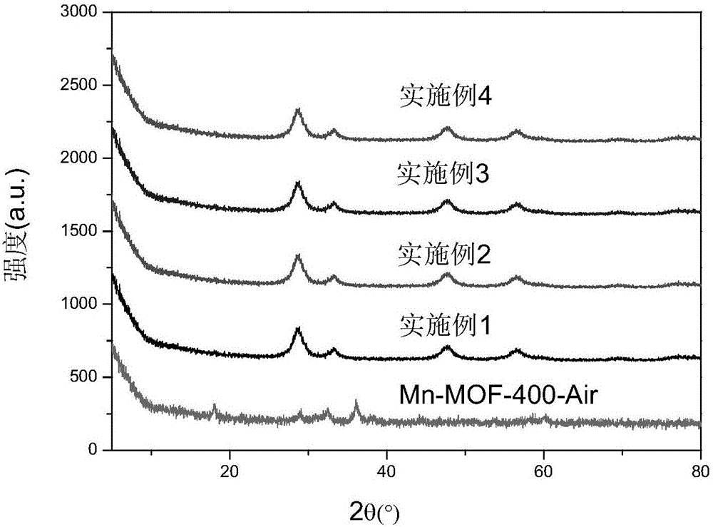
Embodiment 1

[0049] 520 μL of 50% Mn(NO 3 ) 2 solution and 1.94gCe(NO 3 ) 3 ·6H 2 O was added to DMF, 0.8mL of formic acid was added, and the solution was oscillated for 30min by ultrasonic wave until the solution was evenly mixed; then, the solvothermal synthesis reaction was carried out at 80°C for 24h to obtain the Mn-Ce bimetallic organic framework crystal material; the crystal material was washed with DMF and diethyl ether Finally, centrifugal filtration at 5000r / min was used for 5 minutes, and the product was dried in an oven at 100°C; the dried sample was carbonized in a muffle furnace with programmable temperature rise, and the temperature rise process was as follows: (1) Heating stage: first Raise the temperature from room temperature to 400°C with a heating rate of 1°C / min; (2) constant temperature stage: then keep at 400°C for 2 hours; (3) cooling stage: finally let the muffle furnace temperature drop from 400°C to 35.0°C , the cooling rate was 10°C / min, and a low-temperatur...

Embodiment 2

[0051] 520 μL of 50% Mn(NO 3 ) 2 solution and 3.88gCe(NO 3 ) 3 ·6H 2 O was added to DMF, 0.9mL formic acid was added, ultrasonically oscillated for 30min until the solution was mixed uniformly; then solvothermal synthesis reaction was carried out at 90°C for 20h to obtain the Mn-Ce bimetallic organic framework crystal material; the crystal material was subjected to DMF and diethyl ether in sequence Washing, using 5500r / min centrifugal filtration for 7min, put the product into a 100°C oven for drying; put the dried sample into a programmable temperature-raising muffle furnace for carbonization, and the temperature-programming process is as follows: (1) Heating stage: first Raise the temperature from room temperature to 400°C with a heating rate of 1°C / min; (2) constant temperature stage: then keep at 400°C for 2 hours; (3) cooling stage: finally let the muffle furnace temperature drop from 400°C to 35.0°C , the cooling rate was 10°C / min, and a low-temperature denitration ca...

Embodiment 3

[0053] 520 μL of 50% Mn(NO 3 ) 2 solution and 5.82gCe(NO 3 ) 3 ·6H 2 O was added to DMF, 1.0 mL of formic acid was added, ultrasonically oscillated for 30 min until the solution was evenly mixed; then solvothermal synthesis was carried out at 100°C for 16 h to obtain a Mn-Ce bimetallic organic framework crystal material; the crystal material was subjected to DMF and diethyl ether in sequence Washing, centrifugal filtration at 6000r / min for 8min, the product was dried in an oven at 100°C; the dried sample was carbonized in a muffle furnace with programmable temperature rise, and the temperature rise process was as follows: (1) Heating stage: first Raise the temperature from room temperature to 400°C with a heating rate of 1°C / min; (2) constant temperature stage: then keep at 400°C for 2 hours; (3) cooling stage: finally let the muffle furnace temperature drop from 400°C to 35.0°C , the cooling rate was 10°C / min, and a low-temperature denitration catalyst based on carbonized...


PUM

PropertyMeasurementUnit
specific surface areaaaaaaaaaaa
pore sizeaaaaaaaaaa

Abstract

The invention discloses a low-temperature denitrification catalyst based on carbonized MOFs (metal organic frameworks) and a preparation method thereof; the method comprises the steps of (1) adding Mn(NO3)2 solution and Ce(NO3)3.6H2O and Ce(NO3)3.6H2O into DMF (dimethylformamide), and adding formic acid; (2) ultrasonically shaking until a solution is mixed well; (3) subjecting a mixed solution to solvothermal synthetic reaction to obtain Mn / Ce-based metal organic framework crystal material; (4) washing the crystal material sequentially with DMF and ethyl ether, centrifugally filtering and extracting a product, and drying in an oven; (5) carbonizing a dried sample in a muffle furnace to obtain the low-temperature denitrification catalyst. The catalyst herein has good low-temperature denitrification activity; compared with existing low-temperature SCR (selective catalytic reduction) catalytic material, the catalyst has greatly improved resistance to SO2 poisoning; after SO2 is introduced, the catalyst has denitrification activity that rises instead of falling; therefore, the catalyst has great potential application prospect in terms of low-temperature SCR denitrification.

Description

technical field [0001] The invention relates to the technical field of nitrogen oxide removal, in particular to a carbonized MOFs-based low-temperature SCR denitration catalyst for removing nitrogen oxides emitted from coal-fired thermal power plants and a preparation method thereof. Background technique [0002] Selective catalytic reduction (SCR) denitrification technology has become the main technology for NOx emission control in power plants due to its good selectivity and high denitrification efficiency. Denitrification catalyst is the core of denitrification technology. Vanadium-titanium series catalyst is the most widely used denitrification catalyst at present, and its operating temperature is in the temperature range of 300-400°C. Therefore, the SCR reactor needs to be installed before desulfurization and dust removal. The arrangement results in a large amount of SO in the flue gas passing through the SCR reactor 2 And dust will deactivate the catalyst and reduce t...

Claims


Application Information

Patent Timeline
Patent Type & Authority Applications(China)
IPC IPC(8): B01J31/12B01D53/86B01D53/56
CPCB01D53/8628B01J31/12
Inventor 夏启斌范美玲吕道飞陈永伟肖静奚红霞李忠
Owner SOUTH CHINA UNIV OF TECH
Learn More