Asymmetric clamping device and experimental method for sheet compressing

A clamping device, asymmetric technology, applied in the direction of measuring device, using stable tension/pressure testing material strength, instruments, etc., can solve problems such as instability and wrinkling

Active Publication Date: 2017-01-25
NORTHWESTERN POLYTECHNICAL UNIV
View PDF9 Cites 16 Cited by
  • Summary
  • Abstract
  • Description
  • Claims
  • Application Information

AI Technical Summary

Problems solved by technology

[0005] In order to overcome the problem of large deformation of the thin plate compression instability wrinkling, and to achieve full restraint on the side of the sample, while eliminating the friction in the width direction of the gauge section of the sample, the present invention proposes an asymmetric clamping device for thin plate compression and an experimental method

Method used


Image

  • Asymmetric clamping device and experimental method for sheet compressing
  • Asymmetric clamping device and experimental method for sheet compressing
  • Asymmetric clamping device and experimental method for sheet compressing

Examples


Embodiment 1

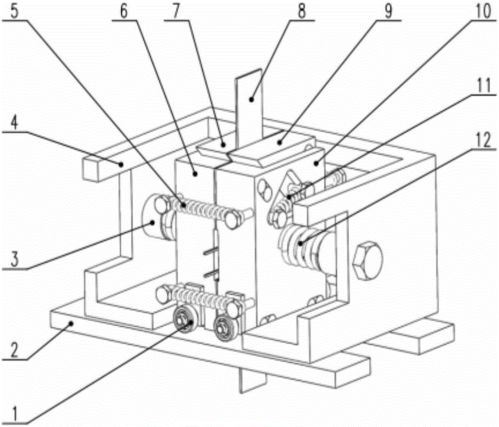
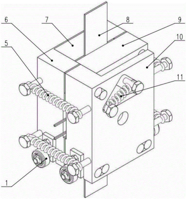
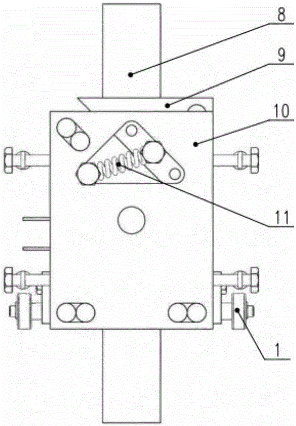
[0139] This embodiment is an asymmetric clamping device for thin plate compression, including a guide wheel 1, a test machine work surface 2, a central spring seat 3, a central spring support 4, side springs 5, a first clamping plate 6, a first Slide block 7, second slide block 9, second clamping plate 10, return spring 11, center spring 12, guide key 14, guide wheel frame 15, slide block guide rod 16 and splint guide rod 17.

[0140] The first clamping plate 6 and the second clamping plate 10 are located in the draw-in slots on the bottom plate of the central spring support 4, are installed on the working table of the experimental machine, and are respectively fixed on the central spring support by the central spring 12 4 on. The working surface of the installed first clamping plate 6 is opposite to the working surface of the second clamping plate 10 to clamp the thin plate in the middle. There are four guide wheels 1, which are divided into two groups, one group is inserted...

Embodiment 2

[0159] This embodiment is a method for carrying out a thin plate compression test using the asymmetric clamping device described in Embodiment 1. The thickness of the sample is 1 mm, and the material is DP600. The measuring lug 39 protrudes 10 mm outside the device, and the sample extends up and down 12 mm outside the device for clamping by the chuck of the testing machine. The sample is asymmetrical up and down. The upper part of the non-gauge length section is 15mm longer than the lower part. The upper part of the non-gauge length section bears the friction force in the width direction, which can eliminate the friction force in the width direction caused by the movement of the slider. Impact.

[0160] The concrete process of this embodiment is:

[0161] Step 1. Install the experimental device, the specific process is as follows:

[0162] Ⅰ. Place the central spring support 4 on the working table 2 of the testing machine, so that the center of the collet of the multifunctio...

Embodiment 3

[0191] This embodiment is a thin plate tension-compression experiment carried out using the asymmetric clamping device; the stretching amount is 5 mm, and the compression amount is 10 mm.

[0192] The sample thickness of this embodiment is 1 mm, and the material is DP600. The measuring lug 39 protrudes 10 mm outside the device, and the sample extends up and down 12 mm outside the device for clamping by the chuck of the testing machine. The sample is asymmetrical up and down. The upper part of the non-gauge length section is 15mm longer than the lower part. The upper part of the non-gauge length section bears the friction force in the width direction, which can eliminate the friction force in the width direction caused by the movement of the slider on the sample. Impact.

[0193] The concrete steps of the thin plate continuous tension-compression experiment of the present embodiment are as follows:

[0194] Step 1. Install the experimental device, the specific process is as f...


PUM

PropertyMeasurementUnit
diameteraaaaaaaaaa
lengthaaaaaaaaaa
thicknessaaaaaaaaaa

Abstract

An asymmetric clamping device and experimental method for sheet compressing are provided; two clamp plates of the asymmetric clamping device are positioned in retaining grooves in a center spring support baseplate, lateral pressure is applied to a sheet through the clamp plates and sliders such that the sheet wrinkles in the thickness direction and loses stability in the width direction; two return springs are each fixed between the corresponding clamp plate and slider; tension springs are connected to the lateral sides of the two clamp plates to provide uniform symmetric pressure for the clamp plates; lateral pressure is applied through the springs, a sample is given planar clamping force through the clamping device, the sample is kept moving evenly in the thickness direction, it is guaranteed that a clamping gap may automatically adjust with changes in sheet thickness; a slider movement area is positioned in a sample non-standard distance segment, the transverse frictional force on the sample may not affect a standard distance segment, and the impact of slider movement induced width-directional frictional force upon experimental results is eliminated; the invention provides three travel options, and various sheet tensioning and compressing experimental needs can be met.

Description

technical field [0001] The invention relates to an asymmetric clamping device for thin plate compression, which belongs to the technical field of plate forming testing. Background technique [0002] Sheet metal forming is an important part of the material processing field, has become one of the pillar industries of national economic development, occupies an important position in the automobile industry and aerospace industry, and is an important part of advanced manufacturing technology. Among them, the performance of the sheet is an important basis for determining the parameters of the forming process. It is of great significance to master the basic material performance parameters such as the yield limit of the sheet, the tensile stress-strain curve, and the tension-compression stress-strain curve. [0003] With the development of thin-walled lightweight component manufacturing technology, the requirements for the forming accuracy of the sheet are getting higher and higher....

Claims


Application Information

Patent Timeline
Patent Type & Authority Applications(China)
IPC IPC(8): G01N3/04G01N3/08
CPCG01N3/04G01N3/08G01N2203/0016G01N2203/0282
Inventor 詹梅盛凯王贤贤郭靖雷新鹏
Owner NORTHWESTERN POLYTECHNICAL UNIV
Why Eureka
Try Eureka