Resistor manufacturing method

A manufacturing method and technology of resistors, applied in the direction of resistance manufacturing, resistors, thin film resistors, etc., can solve the problems of substrate shedding, affecting resistance strain gauges, unable to meet high resistance values, etc., to increase adhesion, avoid falling off, The effect of improving resistance and temperature coefficient and bidirectional stability at high temperature and low temperature

Inactive Publication Date: 2017-01-25
北京埃德万斯离子束技术研究所股份有限公司
View PDF4 Cites 3 Cited by
  • Summary
  • Abstract
  • Description
  • Claims
  • Application Information

AI Technical Summary

Problems solved by technology

However, there are still the following problems in actual manufacturing: ①When the thickness of the alloy foil is large, it will fall off from the substrate due to excessive internal stress, which seriously affects the application of the resistance strain gauge; ②The nickel-chromium alloy foil has a large The temperature coefficient of resistance is not suitable for measuring strain in an environment with severe temperature changes. It is necessary to reduce the temperature coefficient of resistance of the alloy foil, especially the stress measurement characteristics at high temperatures, and expand the temperature range of the measurement; ③ widen the temperature range of the alloy foil Strain range, so that the relative change of thin film resistors and chip resistors has a linear relationship with strain in the widest possible strain range
[0004] Existing thin film resistors and chip resistors are usually processed on alloy foils with a thickness > 2.5 μm, and the processed alloy foils are only suitable for manufacturing thin film resistors and chip resistors with a resistance value < 200KΩ, which cannot satisfy The need for higher resistance

Method used


Image

  • Resistor manufacturing method
  • Resistor manufacturing method
  • Resistor manufacturing method

Examples


Embodiment Construction

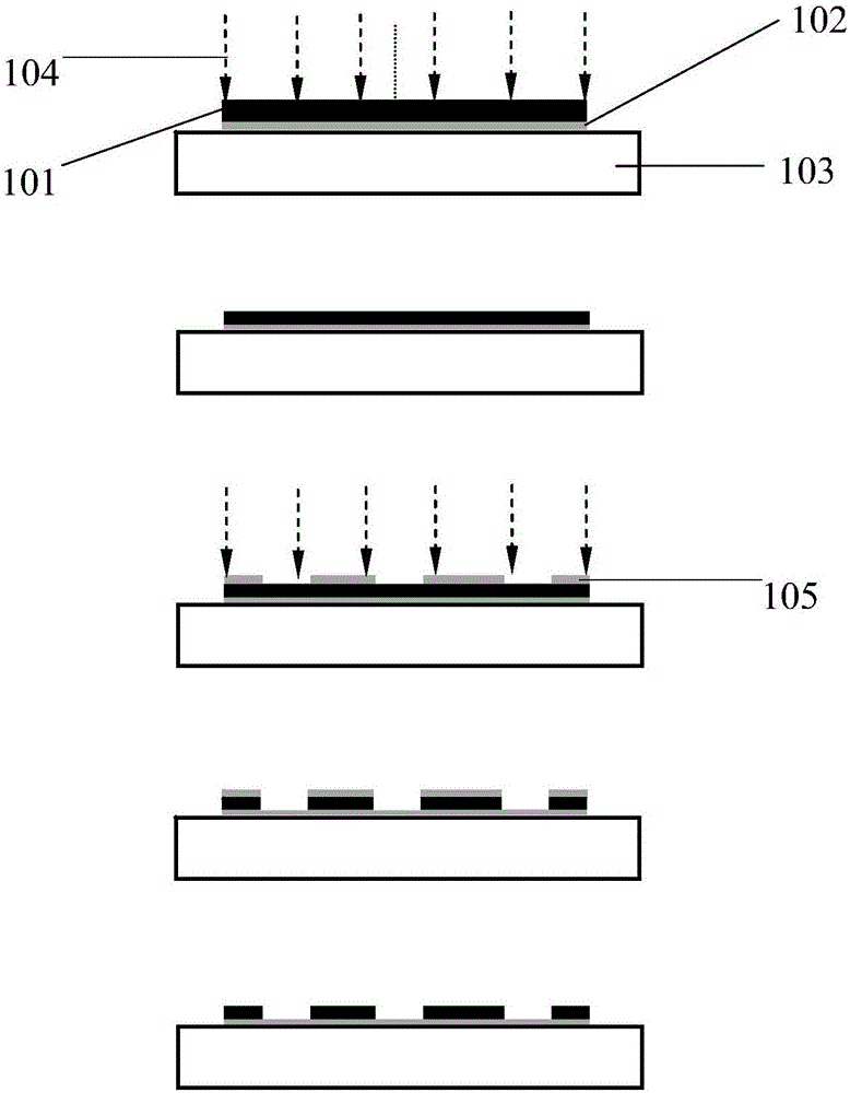
[0017] Hereinafter, embodiments of the present disclosure will be described with reference to the drawings. It should be understood, however, that these descriptions are exemplary only, and are not intended to limit the scope of the present disclosure. Also, in the following description, descriptions of well-known structures and techniques are omitted to avoid unnecessarily obscuring the concepts of the present disclosure.

[0018] Various structural schematic diagrams according to embodiments of the present disclosure are shown in the accompanying drawings. The figures are not drawn to scale, with certain details exaggerated and possibly omitted for clarity of presentation. The shapes of the various regions and layers shown in the figure, as well as their relative sizes and positional relationships are only exemplary, and may deviate due to manufacturing tolerances or technical limitations in practice, and those skilled in the art will Regions / layers with different shapes, ...


PUM

PropertyMeasurementUnit
thicknessaaaaaaaaaa
thicknessaaaaaaaaaa
thicknessaaaaaaaaaa

Abstract

The invention discloses a resistor manufacturing method, comprising: providing a metal foil; thinning the metal foil; producing photoresist on the metal foil, etching the metal foil, and forming a preset pattern on the metal foil; cleaning the residual photoresist to obtain a resistor. The method enables improved resistance for the resistor and increased temperature coefficient and high-temperature and low-temperature bidirectional stability, adhesion with an insulating base is improved, separation from the insulating base due to excessive internal stress is avoided, and the applicable range of resistance strain gauges is widened.

Description

technical field [0001] The invention relates to the technical field of semiconductors, in particular to a method for manufacturing high-resistance thin-film resistors or chip resistors by ion beam secondary etching. Background technique [0002] The resistance strain gauge is an element used to measure the surface strain of a component, mainly composed of a sensitive grid and a substrate. The sensitive grid, which is a film resistor with pins and a chip resistor without pins, is the main part of the resistance strain gauge, and its function is to convert the measured strain into the resistance change. The substrate is used to support and protect the sensitive grid and keep the insulation between the sensitive grid and the components to be tested. [0003] Nickel-chromium alloy foils are widely used as thin film resistors and chip resistors in resistance strain gauges because of their high resistivity, low temperature coefficient of resistance, high strain sensitivity coeffi...

Claims


Application Information

Patent Timeline
Patent Type & Authority Applications(China)
IPC IPC(8): H01C7/00H01C17/00H01L21/3213
CPCH01C7/00H01C7/006H01C17/00H01C17/003H01L21/32136
Inventor 刁克明
Owner 北京埃德万斯离子束技术研究所股份有限公司
Why Eureka
Try Eureka