
Dual-port dual-frequency dual-circular polarized micro-strip array antenna

A technology of microstrip array and dual circular polarization, which is applied in the field of satellite antennas, can solve the problems of high antenna profile, high profile of dual frequency dual circular polarization antenna, difficulty in achieving dual frequency dual circular polarization performance, etc., to improve impedance Bandwidth and axial ratio bandwidth, good dual-frequency dual-circular polarization performance, convenient expansion into large arrays

Active Publication Date: 2017-01-25
中天引控科技股份有限公司
View PDF4 Cites 23 Cited by
  • Summary
  • Abstract
  • Description
  • Claims
  • Application Information

AI Technical Summary

Problems solved by technology

A simple method is to implement it through a reflector antenna and a feed horn, but this antenna has a high profile and is not easy to integrate with the system; and a general microstrip antenna can also achieve dual-frequency dual-circular polarization by stacking multi-layer structures. However, this kind of antenna has complex structure, difficult processing and high cost
The "single-layer dual-frequency circularly polarized microstrip array antenna" disclosed by the Chinese patent (application number: 201410649033.9, publication date: 2015.2.4) passes the working frequency f 1 , f 2 The two circularly polarized radiation patches are respectively connected to a section of microstrip line, and the two sections of microstrip line are connected at one point. By setting the position of the connection point, the two patches can work normally at their respective frequencies without affecting each other. However, This method operates at two operating frequencies f 1 , f 2 closer together (ie f 2 / f 1 When it is close to 1), it cannot be isolated, and it is difficult to achieve dual frequency and dual circular polarization performance
[0005] Therefore, there are problems in the existing technology: the dual-frequency dual-circular polarization antenna has a high profile, narrow frequency band, multi-layer complex structure, and it is difficult to realize dual-frequency dual circular polarization on two operating frequencies that are close together

Method used


Image

  • Dual-port dual-frequency dual-circular polarized micro-strip array antenna
  • Dual-port dual-frequency dual-circular polarized micro-strip array antenna
  • Dual-port dual-frequency dual-circular polarized micro-strip array antenna

Examples


Embodiment

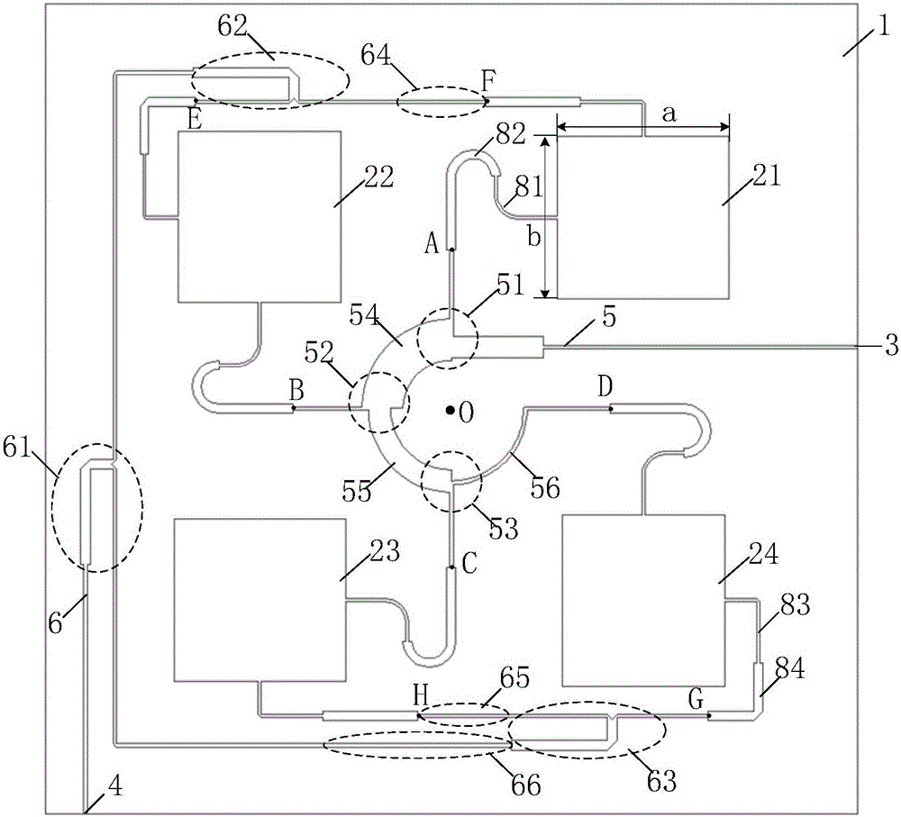
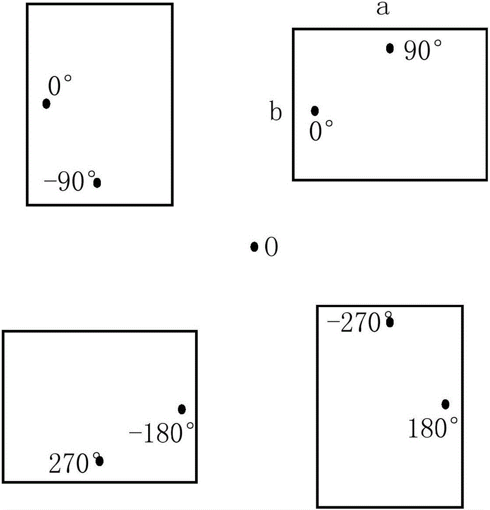
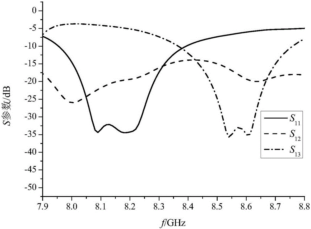
[0046] Such as figure 1 2×2 array shown, dual-frequency operating frequency f 1 =8.2GHz, f 2 = 8.6GHz, frequency ratio f 2 / f 1 = 1.05. The dual-frequency shared radiation patch is a rectangular patch, with a side length of 11.66mm, corresponding to the low-frequency resonance f 1 , the b side length is 11.04mm, corresponding to the high frequency resonance f 2 . The dual-frequency shared radiation patch is a linearly polarized unit, which generates TM at two operating frequencies 01 Die and TM 10 mold. Using sequential rotation feeding technology, 4 rectangular patches are rotated sequentially to form a sub-array, and the working frequency is f 1 , to feed the first feed port 3, the current flows in from the feed port 3, point A, point B, point C and point D generate relative feed phases of 0°, -90°, -180°, -270° , the arrangement makes an array of four patches form a right-handed circularly polarized wave; the operating frequency is f 2 , to feed the second feed p...


PUM


Abstract

The invention discloses a dual-port dual-frequency dual-circular polarized micro-strip array antenna, comprising a dielectric substrate (1), four dual-frequency shared radiation patches (21, 22, 23, 24) arranged on the upper surface of the dielectric substrate (1), a first feeding port (3) and a second feeding port (4), wherein a first-frequency output end of the four radiation patches (21, 22, 23, 24) is connected with the first feeding port (3) through a series-feed power division network (5), and a second-frequency output end of the four radiation patches (21, 22, 23, 24) is connected with the second feeding port (4) through a parallel-feed power division network (6). The dual-port dual-frequency dual-circular polarized micro-strip array antenna disclosed by the invention is simple in structure with a low section plane, good in bandwidth and low in cross polarization, can be expanded into a large-scale array conveniently, and has unique advantages for dual-circular polarization application of two frequency points with close frequencies, and the two ports have good isolation.

Description

technical field [0001] The invention belongs to the technical field of satellite antennas, in particular to a dual-port dual-frequency dual-circular polarization microstrip array antenna with simple structure, low profile, wide bandwidth, low cross polarization and good isolation. Background technique [0002] Because of its small size, light weight, low cost, and easy integration, microstrip antennas have become an important branch of the antenna field. Circularly polarized antennas can receive arbitrary polarized waves and have strong anti-interference performance, and are more and more widely used in satellite and communication systems. Circularly polarized microstrip antennas have the advantages of both, and have broad application prospects. [0003] The conventional circularly polarized microstrip antenna is a high-Q resonant antenna with a narrow operating frequency band. The methods to widen the circular polarization bandwidth mainly include: using broadband microst...

Claims


Application Information

Patent Timeline
IPC IPC(8): H01Q21/24H01Q1/50
CPCH01Q1/50H01Q21/24
Inventor 汪敏王道雨吴文徐诺仵娜陈春红
Owner 中天引控科技股份有限公司
Learn More