Imaging spectrometer based on joint spatiotemporal modulation and mzi optical waveguide array
An imaging spectrometer and a combined modulation technology are applied in the field of imaging spectrometers to achieve the effects of reducing the size of the chip, reducing the volume and improving the detection sensitivity
- Summary
- Abstract
- Description
- Claims
- Application Information
AI Technical Summary
Problems solved by technology
Method used
Image

Examples
Embodiment 1
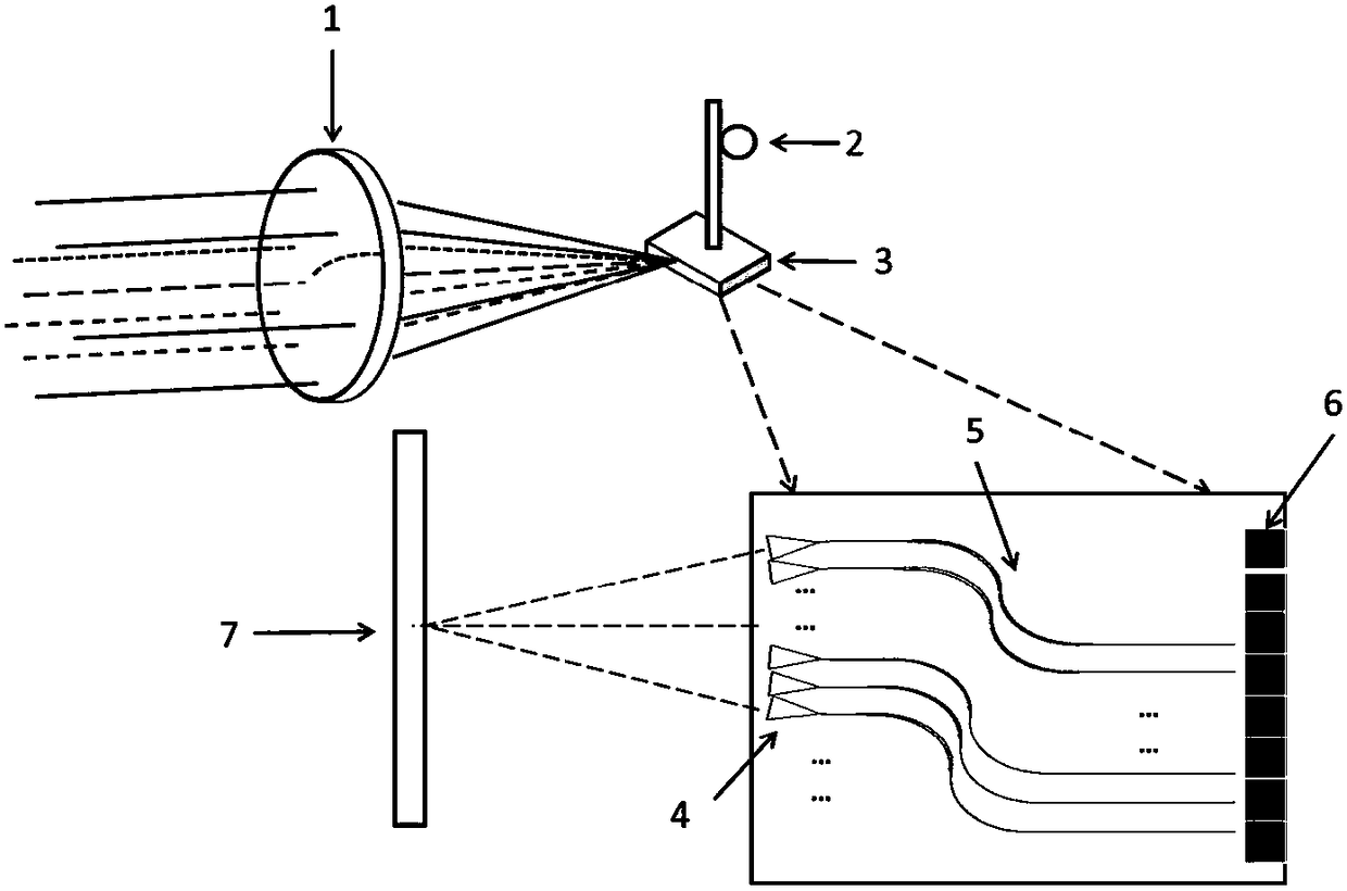
[0061] Specifically, for example, such as figure 2 As shown, the imaging system such as the front mirror 1 is placed at the bottom of the aircraft, and it is collected facing directly below. The imaging image plane of the front mirror 1 imaging system is an N×M image plane, and the push-broom direction of the aircraft is the upward push-broom in the figure. The imaging image plane corresponds to a row of N pixels corresponding to the parallel push-broom direction, and the input ports of the N speckle converters in the speckle converter array 4 are aligned with the N pixels along the row direction on the corresponding receiving imaging image plane The input ports of the N MZIs of the MZI array 5 receive and transmit the optical signals of the N picture elements in the row direction, and the distance between the input ports between the MZIs in the MZI array 5 and the distance between the pixels of the imaging image plane along the row direction the same spacing;
[0062] There...
Embodiment 2
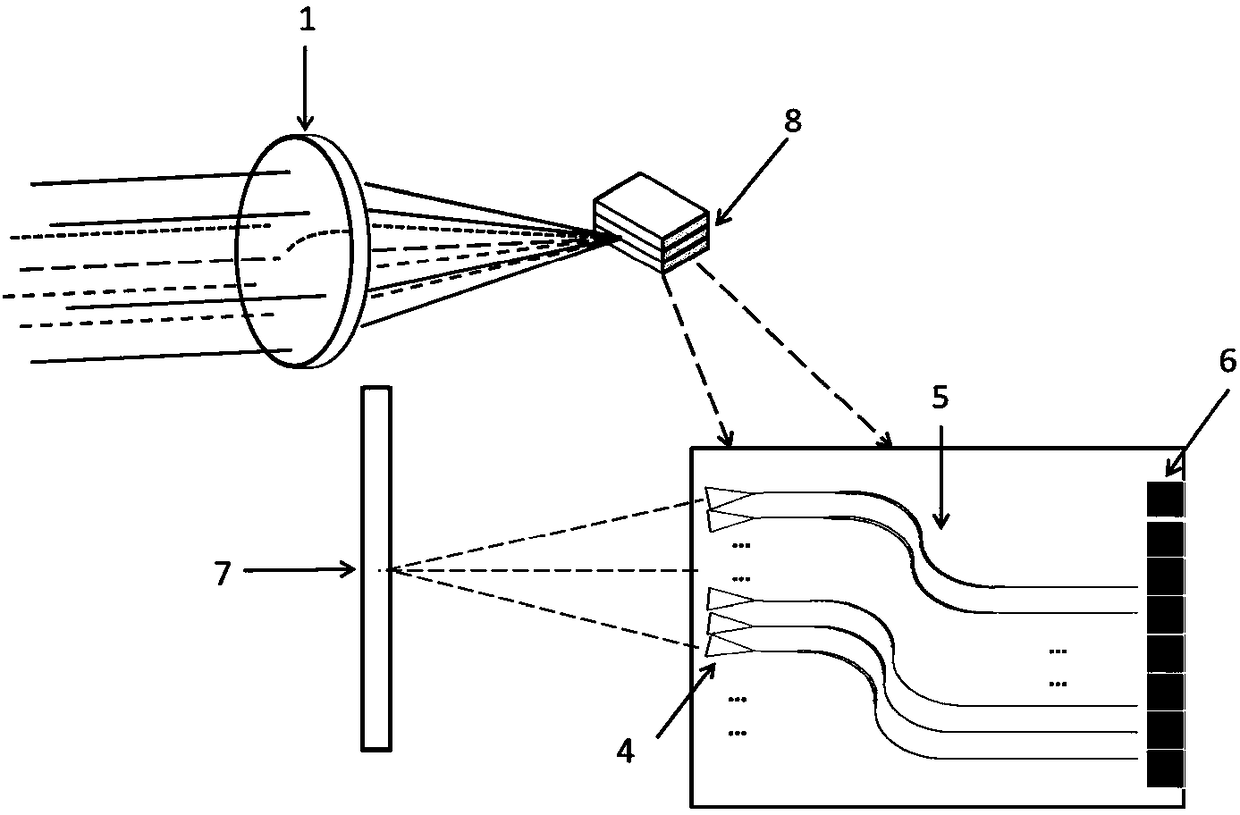
[0065] Specifically, for example, such as image 3 As shown, the imaging system such as the front mirror 1 is placed at the bottom of the aircraft, and it is collected facing directly below. The imaging image plane of the front mirror 1 imaging system is an N×M image plane, and the push-broom direction of the aircraft is the upward push-broom in the figure. The imaging image plane is a row of N pixels corresponding to the parallel push-broom direction.
[0066] The input ports of the N speckle converters in the speckle converter array 4 of a piece of interferometric spectrometer chip 3 are aligned to receive the optical signals of N picture elements along the row direction on the imaging image plane, and the input ports between the MZIs in the MZI array 5 The pitch is the same as the pitch between the pixels of the imaging image plane along the row direction; the stacking direction of the M interferometric spectrometer chip 3 of the three-dimensional chip 8 is aligned with the...
Embodiment 3
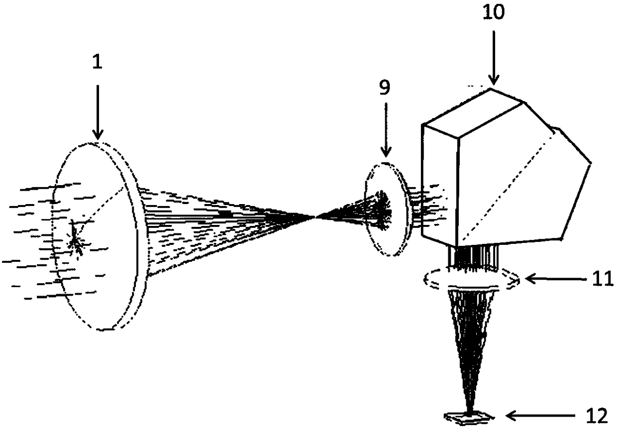
[0070] Specifically, for example, such as image 3 As shown, the imaging system such as the front mirror 1 is placed at the bottom of the aircraft, and it is collected facing directly below. The imaging image plane of the front mirror 1 imaging system is an N×M image plane, and the push-broom direction of the aircraft is the upward push-broom in the figure. The imaging image plane is a row of N pixels corresponding to the parallel push-broom direction.
[0071] The input ports of the M speckle converters in the speckle converter array 4 of a piece of interferometric spectrometer chip 3 are aligned to receive the optical signals of M pixels along the column direction on the imaging image plane, and the input ports between the MZIs in the MZI array 5 The pitch is the same as the pitch between the pixels of the imaging image plane along the row direction; the stacking direction of the N interferometric spectrometer chips 3 of the three-dimensional chip 8 is aligned with the optic...
PUM
 Abstract
Description
Claims
Application Information
 - Generate Ideas
- Intellectual Property
- Life Sciences
- Materials
- Tech Scout
- Unparalleled Data Quality
- Higher Quality Content
- 60% Fewer Hallucinations
Browse by: Latest US Patents, China's latest patents, Technical Efficacy Thesaurus, Application Domain, Technology Topic, Popular Technical Reports.
© 2025 PatSnap. All rights reserved.Legal|Privacy policy|Modern Slavery Act Transparency Statement|Sitemap|About US| Contact US: help@patsnap.com