Blood flow divider

A shunt and blood technology, applied in the field of blood flow shunt, can solve the problems of different sensitivity and acceptability, difficulty in grasping the appropriate dose for patients, slow onset of action, etc., to avoid side effects of increased burden on the heart, easy to transform and manufacture , lowering the effect of high blood pressure

Active Publication Date: 2017-02-08
SHANGHAI CONFLOW MEDTECH CO LTD
View PDF6 Cites 5 Cited by
  • Summary
  • Abstract
  • Description
  • Claims
  • Application Information

AI Technical Summary

Problems solved by technology

However, drug control has the following disadvantages: ①Slow onset, most drugs take more than one hour to take effect, and the fastest takes tens of minutes, which is obviously slow for urgent control and sudden increase of blood pressure; ②Cannot achieve real-time control
Medication control depends on blood pressure detection. Patients can adjust their medications only when they detect blood pressure fluctuations. However, it is obviously impossible and inconvenient to mon

Method used


Image

  • Blood flow divider
  • Blood flow divider
  • Blood flow divider

Examples


Embodiment 1

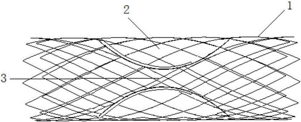
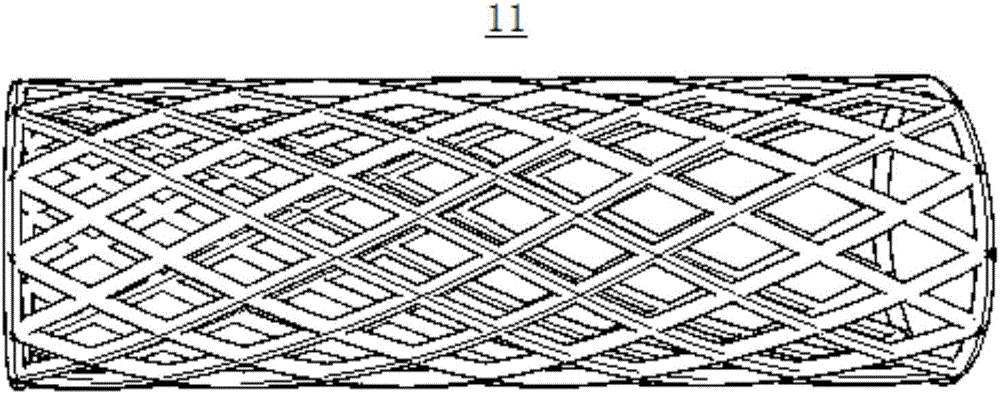
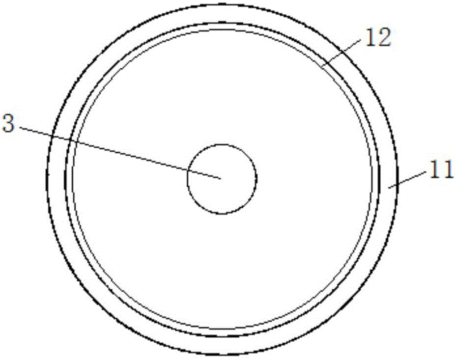
[0038] Such as figure 1 Shown is a schematic structural view of a preferred embodiment of the blood shunt according to the present invention, which is used to connect arteries (left in the figure) and veins (right in the figure) blood vessels, including a tubular component 1 and a flow control component 2. The flow control part 2 is set inside the tubular part 1, and the flow control part 2 has a through hole 3 arranged along the axial direction of the tubular part inside, so that there is always blood flow in the working position Through this, the risk of thrombus formation in the shunt can be reduced, and the size of the through hole 3 will change in real time with the pressure it is subjected to; when the blood pressure increases, the through hole 3 will also change accordingly. Larger, and then the blood flow through the through hole becomes larger, and vice versa.

[0039] Furthermore, the through hole 3 has an opening threshold, that is, when the blood pressure is less ...

Embodiment 2

[0053] The following steps can be adopted when the blood flow separator provided by the present invention is implanted:

[0054] 1) Establish a vascular channel between human arteries and veins through surgical operation or minimally invasive intervention;

[0055] 2) Compress the blood flow shunt outside the body, load and transport it into the system;

[0056] 3) Send the delivery system into the vascular channel along the peripheral vein;

[0057] 4) Release the blood flow shunt so that it is fully opened in the blood vessel channel and plays a role;

[0058] 5) Withdrawal from the delivery system.


PUM

PropertyMeasurementUnit
The inside diameter ofaaaaaaaaaa
Lengthaaaaaaaaaa

Abstract

The invention discloses an arterial-venous blood flow divider capable of controlling blood pressure fluctuation quickly and effectively in real time. The blood flow divider can divide the arterial blood flow to the vein when the blood pressure rises so as to prevent further rise of the blood pressure and achieve an aim of controlling the blood pressure fluctuation. The blood flow divider comprises a tubular component and a flow control component, wherein the flow control component is arranged in the tubular component; a through hole along the axial direction of the tubular component is formed in the flow control component; the size of the through hole changes in real time along with the magnitude of pressure, and the blood flow rate changes in real time along with the size change of the through hole; if the through hole becomes larger, the blood flow rate increases along; and if the through hole becomes smaller, the blood flow rate decreases along. Furthermore, the through hole has an open threshold; when the blood pressure is lower than or equal to the threshold, the through hole is kept in a minimum state; and when the blood pressure is higher than the threshold, the through hole becomes larger to be opened.

Description

technical field [0001] The invention relates to a blood flow shunt, in particular to a blood flow shunt for controlling fluctuations in blood pressure. Background technique [0002] Hypertension is a common disease that seriously affects social health. In my country alone, there are about 330 million patients. Cardiovascular and cerebrovascular disease death is the first cause of death in my country, and among all cardiovascular and cerebrovascular disease deaths, hypertension accounts for about 64.0%. The blood pressure of the human body is not static, but there are fluctuations (or variability). Strenuous activity and mood swings can increase blood pressure levels and blood pressure fluctuations, while rest, sleep and digestion can significantly reduce them. Blood pressure fluctuations increase with age. Factors such as temperature changes, blood volume changes, diet changes, and irrational medications also have an impact on blood pressure fluctuations. A large number ...

Claims


Application Information

Patent Timeline
IPC IPC(8): A61F2/07A61F2/06A61B17/00
CPCA61B17/00A61F2/07A61F2002/068
Inventor 潘文志沈雳程蕾蕾钱菊英葛均波
Owner SHANGHAI CONFLOW MEDTECH CO LTD
Why Eureka
Try Eureka