Take-off and landing platform for aircraft

A landing platform and aircraft technology, applied in the field of multi-axis aircraft landing platform, can solve the problems of increased flight resistance, unfavorable multi-axis aircraft take-off and landing, UAV take-off dependence, etc.

Inactive Publication Date: 2017-02-08
ZHUHAI PANSHI ELECTRONICS TECH CO LTD
View PDF6 Cites 22 Cited by
  • Summary
  • Abstract
  • Description
  • Claims
  • Application Information

AI Technical Summary

Problems solved by technology

Obviously, the takeoff of the drone depends on the weather conditions, and it still cannot take off in a windy environment
This system can only solve the problem of UAV take-off in good weather environment. In the environment of strong wind and waves, the problem of UAV take-off and landing is still not solved.
In addition, the plate electromagnet and the electromagnet drive module connected to it are fixed on the ship, and the magnetic plate is fixed on the tripod of the drone. Due to the large span of the tripod of the drone, a large support is required Therefore, the area of ​​the flat electromagnet will be very large, not only the weight is heavy, the manufacturing cost is high, but also requires more power to maintain the fixation of the drone, which is poor in practicability
When the take-off and landing platform is set on the land driving device, the undulations of the road surface will cause the driving device and the landing platform to be bumpy, which is not conducive to the take-off and landing of the multi-axis aircraft
[0006] Existing multi-axis aircraft basically only adjust the flight attitude by changing the rotor speed. Translational flight needs to tilt the fuselage, thus increasing the windward area of ​​the fuselage, resulting in an increase in flight resistance, making the multi-axis aircraft slow in response and poor in maneuverability , the frequent acceleration and deceleration of the motor causes a large loss of kinetic energy, large heat loss of the motor, and low efficiency
Under the action of high-speed airflow, it is difficult to take off and land safely
Before taking off on the landing platform impacted by the high-speed airflow, the multi-axis aircraft has no protection measures, not only is it easy to be blown off by the high-speed airflow, but also cannot achieve safe and stable mobile take-off and landing

Method used


Image

  • Take-off and landing platform for aircraft
  • Take-off and landing platform for aircraft
  • Take-off and landing platform for aircraft

Examples


Embodiment 2

[0049] The difference between this embodiment and the first embodiment lies in the first tilting driving device and the second tilting driving device.

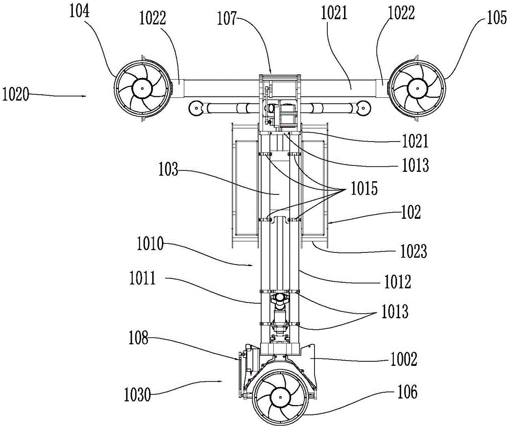
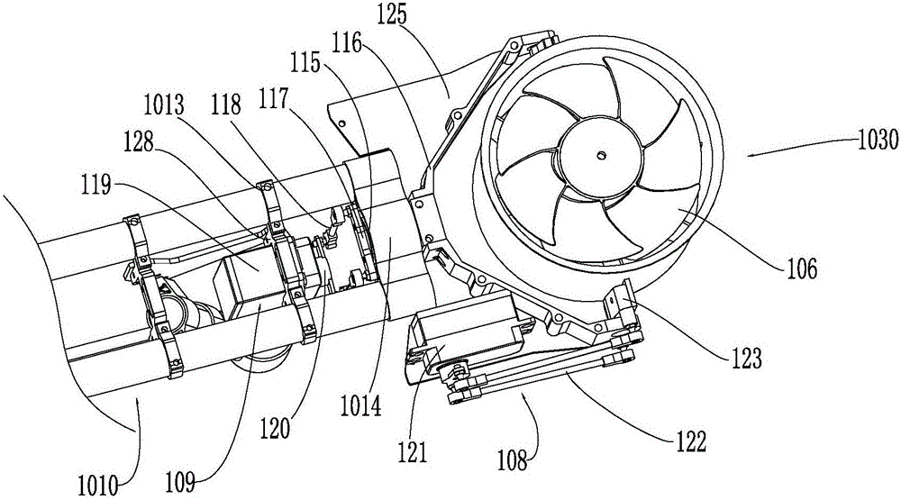
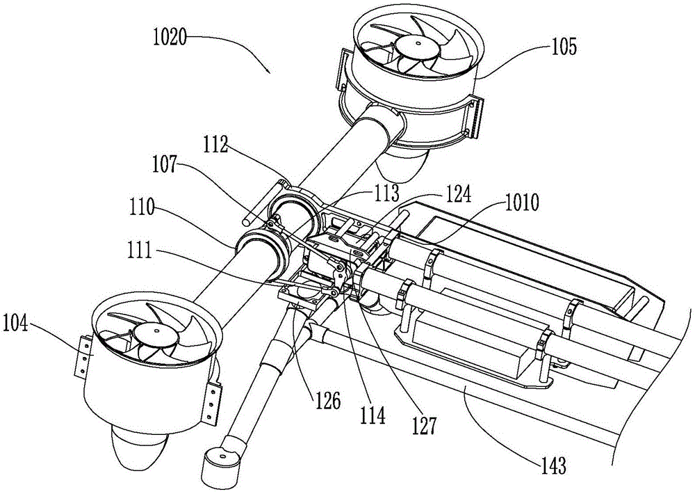
[0050] like Figure 5 As shown, the first tilting drive device 200 includes: a fixed frame 201, a steering gear 202, a steering gear output synchronous pulley 203, a synchronous belt 204, and a synchronous pulley 205, and the first end of the fixed frame 201 is rotatably supported by a bearing 206. The first machine arm 2020, the second end opposite to the first end of the fixed frame 201 is connected with the frame 2010 by screws, the third end of the fixed frame 201 located on the lower side is connected with the tripod by screws, and the steering gear 202 is positioned by The column is connected with the fixed frame 201, and the steering gear output synchronous pulley 203 is connected with the synchronous pulley 205 fixed on the first machine arm 2020 through the synchronous belt 204, so that the first machine arm 2020 tilt...

Embodiment 1

[0053] like Figure 7 As shown, the landing platform 1000 includes a fixed plate 810 and an attitude adjustment seat 900 . The attitude adjustment seat 900 has a Stewart-style base 910 with six degrees of freedom. An annular buffer rubber pad 920 as a buffer portion is disposed between the fixed plate 810 and the attitude adjustment seat 900 . The base 910 includes a lower ring frame 911 as a lower frame, six telescopic rods 912 and an upper ring frame 913 as an upper frame. The upper ring frame 913 and the fixing plate 810 are connected by bolts 914 , and the bolts pass through holes in the buffer rubber pad 920 , and the buffer rubber pad 920 is placed between the upper ring frame 913 and the fixing plate 810 . Preferably, the six telescopic rods 912 are electric cylinders or hydraulic cylinders. Apparently, the cushioning part is not limited to the cushioning rubber pad 920, and may also be composed of a plurality of silicone shock-absorbing balls with holes in the middl...

Embodiment 3

[0061] like Figure 13 As shown, the difference between this embodiment and the second embodiment of the landing platform is that the base of the attitude adjustment seat is a base 3910 with three degrees of freedom. The base 3910 includes an upper ring frame 3920 as an upper frame, a lower frame 3930 and a telescopic rod 3940 connecting the upper ring frame 3920 and the lower frame 3930 . The upper ring frame 3920 can tilt around the X and Y axes, and move up and down along the Z axis. The upper end of the telescopic rod 3940 is connected to the upper ring frame 3920 through a universal joint or a ball hinge; the lower end of the telescopic rod 3940 is hinged to the lower frame 3930, and its hinge shaft 3931 is arranged horizontally.


PUM


Abstract

The invention provides a take-off and landing platform for assisting an aircraft to take off and land in a bumpy environment. The take-off and landing platform comprises a fixing plate and an attitude adjustment seat, wherein the fixing plate is used as a platform where the aircraft takes off and lands, and is used for fixing the aircraft before the aircraft takes off; the attitude adjustment seat is mounted on the lower side of the fixing plate and is used for stabilizing a space attitude of the fixing plate; and the attitude adjustment seat is at least provided with two degrees of freedom capable of rotating around the X axis and the Y axis. The multi-axis aircraft is fixed on the fixing plate before taking off, and the attitude adjustment seat dynamically stabilizes the attitude of the aircraft, so that the aircraft can be prevented from swinging back and forth, and good take-off conditions are supplied to taking off; and the stable fixing plate can supply a good landing environment to the multi-axis aircraft.

Description

technical field [0001] The invention relates to a take-off and landing platform of an aircraft, in particular to a take-off and landing platform of a multi-axis aircraft. Background technique [0002] A multicopter usually includes a fuselage, an arm, a flight control device, a power supply, an ESC, a motor, a rotor, and functional sensors. [0003] Electric helicopters usually also include empennage and tail-locking gyroscopes, control devices for controlling the periodic pitch and collective pitch of the rotor pitch, and the control devices include steering gears, swash plates, connecting rods and other components. [0004] Neither multicopters nor electric helicopters are suitable for taking off in a windy environment. At present, quadcopters can fly in winds below level 5; hexacopters can barely fly in winds of levels 6 to 7. The wind speed of category 5 wind is between 8 and 10.7 meters per second, the wind speed of category 6 wind is between 10.8 and 13.8 meters per ...

Claims


Application Information

Patent Timeline
Patent Type & Authority Applications(China)
IPC IPC(8): B64F1/00E01C9/00E01F3/00
CPCE01C9/008E01F3/00B64F1/00
Inventor 何春旺
Owner ZHUHAI PANSHI ELECTRONICS TECH CO LTD
Why Eureka
Try Eureka