
Construction method of ultra-deep underground diaphragm wall in water-rich soft-soil area

A construction method and soft soil technology, applied in sheet pile wall, foundation structure engineering, construction, etc., can solve the problem of slip cracking or collapse of groove wall

Inactive Publication Date: 2017-02-08
CHINA RAILWAY NO 2 ENG GRP CO LTD +1
View PDF3 Cites 26 Cited by
  • Summary
  • Abstract
  • Description
  • Claims
  • Application Information

AI Technical Summary

Problems solved by technology

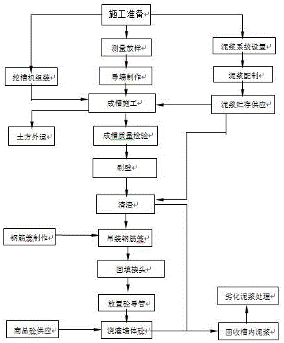
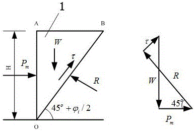
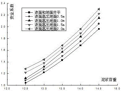
[0009] The object of the present invention is to overcome the problem in the prior art that the groove wall is in an unstable state during the process of forming the groove or before the wall is poured, so that the danger of slipping or collapsing may occur at any time, and to provide a water-rich soft soil The construction method of the ultra-deep underground diaphragm wall in the area, this method introduces the stability analysis method of strength reduction, calculates the safety factor of the groove wall stability on the basis of the finite difference method, and calculates through the parameter reduction cycle, not only can get the groove The ultimate stress and deformation state of the wall, and the stability coefficient of the tank wall will be obtained, which has practical guiding significance for construction. The result is simple and practical and conforms to the habits of the engineering field, effectively ensuring the stability of the tank wall, so that it is safe, high-quality, and fast. to complete the construction

Method used


Image

  • Construction method of ultra-deep underground diaphragm wall in water-rich soft-soil area
  • Construction method of ultra-deep underground diaphragm wall in water-rich soft-soil area
  • Construction method of ultra-deep underground diaphragm wall in water-rich soft-soil area

Examples


Embodiment 1

[0091] This embodiment is applied in the construction process of the ultra-deep underground diaphragm wall in water-rich soft soil areas.

[0092] In this embodiment, the underground space connection project is set as an underground four-story project, and the foundation pit excavation depth is 34m. For excavation construction, the main enclosure structure adopts a 58m deep underground diaphragm wall, the wall thickness is 1.2m, the maximum weight of the steel cage is 116T, and the width is 4.5-6m, a total of 72 pieces. Among them, one-character frame, four Z-character frames, and four L-character frames. H-shaped steel joints are adopted. The area 8m below the bottom of the foundation pit is reinforced with a ground diaphragm wall lattice, and an underground diaphragm wall is set at an interval of 21m in the horizontal direction, with a total of 7 diaphragm walls and 21 diaphragm walls.

[0093] The geological conditions of the project are distributed from top to bottom as ...

Embodiment 2

[0132]This embodiment is applied in the process of configuration and use of wall protection mud.

[0133] The engineering parameters and geological parameters set in this embodiment are the same as those in Embodiment 1.

[0134] During the construction of the underground diaphragm wall, the key process is to excavate the groove. When forming the groove, mud needs to be used to protect the wall, carry slag, cool and lubricate the drilling tools and other functions. The mud should have a series of properties such as physical stability, chemical stability, suitable fluidity, good mud skin forming ability, and appropriate density, in order to meet the above functional requirements. Therefore, scientific configuration and correct use of mud are the key to ensure groove formation.

[0135] (1) Mud preparation

[0136] For the layout of the mud station, due to the complex geological conditions of the ultra-deep underground diaphragm wall to be constructed and the tight constructio...

Embodiment 3

[0170] This embodiment is used in the construction stage of trench excavation.

[0171] The engineering parameters and geological parameters set in this embodiment are the same as those in Embodiment 1.

[0172] Select the appropriate grooving machine. According to the excavation method, the grooving machines include: multi-head auger, punching grab, impact drill, multi-head drill, wheel milling type, disc milling type (milling type), etc.

[0173] The continuous excavation process is used for the construction of the diaphragm wall. In order to ensure the balance of the adjacent conditions on both sides when the trencher cuts the soil, and to ensure that the trench wall is vertical, the diaphragm wall construction plans to use the trench-hopping method. According to the length of the trench section and the The opening width of the slot machine determines the first opening width and the closing width. When using a grab bucket to dig a groove, to make the slot hole vertical, th...


PUM


Abstract

The invention relates to the technical field of civil engineering construction, in particular to a construction method of an ultra-deep underground diaphragm wall in a water-rich soft-soil area. The construction method comprises the following steps: making an analysis and research on the stability of trench walls of the underground diaphragm wall and doing relevant preparations, preparing wall protecting slurry, building a guide wall, performing trenching construction, wall cleaning and sediment removal, manufacturing and hoisting reinforcing cages, backfilling joints between trench sections, and pouring wall concrete. According to the construction method, through a stability analysis method that introduces strength reduction, the security coefficients of stability of the trench walls are calculated based on a finite difference method; through parameter-reduction circular calculations, not only the limit stress and large deformation state of the trench walls but also the stability coefficients of the trench walls are obtained, which has practice guiding significance in construction; and the results are simple and practical and conform to the habits in the engineering field, and the stability requirements of the trench walls are effectively guaranteed, so that the engineering construction can be completed safely and fast with high quality.

Description

technical field [0001] The invention relates to the technical field of civil engineering construction, in particular to a construction method for an ultra-deep underground diaphragm wall in water-rich soft soil areas. Background technique [0002] The underground diaphragm wall is a kind of trenching machine used on the ground for basic engineering. Along the peripheral axis of the deep excavation project, a long and narrow deep trench is excavated under the condition of mud retaining wall. After the trench is cleaned, it is hung in the trench Reinforcement cages, and then use the conduit method to pour underwater concrete to form a unit trough section. In this way, a continuous reinforced concrete wall is built underground as a water interception, anti-seepage, load-bearing, and water-retaining structure. After excavating a deep groove, the soil outside the groove wall has a great influence on the stability of the groove wall, and there is a risk of slippage and collapse. W...

Claims


Application Information

Patent Timeline
Patent Type & Authority Applications(China)
IPC IPC(8): E02D5/18
CPCE02D5/187
Inventor 古存军覃君赵伟
Owner CHINA RAILWAY NO 2 ENG GRP CO LTD
Learn More