

Laser light source system and display apparatus
A laser light source and laser technology, applied in laser devices, semiconductor laser devices, optics, etc., can solve the problems of complex structure and high cost, and achieve the effects of reducing coherence, low cost, and suppressing speckle
- Summary
- Abstract
- Description
- Claims
- Application Information
AI Technical Summary
Problems solved by technology
Method used
Image

Examples
Embodiment 1
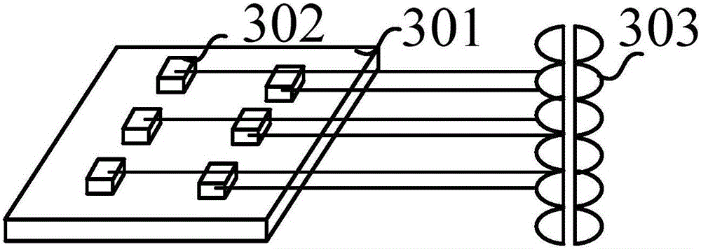
[0067] An embodiment of the present invention provides a laser light source system structure, Figure 3a An exemplary structural block diagram of a laser light source system applicable to the embodiment of the present invention is shown. Such as Figure 3a As shown, it includes: a laser 301 , a heat sink 302 and a homogenizer 303 .
[0068] Such as Figure 3a As shown, the laser 301 includes N laser chips, N is an integer greater than or equal to 1; N laser chips are arranged on the heat sink 302, and the thermal conductivity of at least two laser chips in the heat sink 302 is different; The laser beams emitted by the N laser chips are incident on the homogenizer 303 .
[0069] The emission color of the laser 301 is not limited here, and may be one or any combination of a red laser, a green laser, and a blue laser. The number of heat sinks 302 is also not limited, and may be one or more heat sinks. The material of the heat sink 302 can be copper or aluminum. Doping differ...
Embodiment 2
[0076] Taking the number of heat sinks 302 as an example below, the structure of the laser in the embodiment of the present invention will be described in detail.
[0077] In this embodiment, the number of heat sink 302 is one, and the heat sink 302 can be divided into N regions, wherein at least two of the N regions have different thermal conductivity, and one laser chip is arranged in one region of the heat sink 302 . By encapsulating the laser chip on different parts of the heat sink, due to the difference in thermal conductivity between different parts, there is a temperature difference between the laser chips, and a broadband visible light output is generated to reduce laser coherence.
[0078] In order to generate a large temperature difference among the laser chips, preferably, according to the arrangement sequence of the N regions of the heat sink, the thermal conductivity of the N regions increases linearly or decreases linearly.
[0079] Figure 4a A schematic diag...
Embodiment 3
[0089] Taking the number of heat sinks 302 as N as an example, the laser structure of the embodiment of the present invention will be described in detail below.
[0090] In the embodiment of the present invention, the number of heat sinks 302 is N, at least two of the N heat sinks have different thermal conductivities, and one laser chip is arranged on one heat sink. By packaging N laser chips on N heat sinks, due to the difference in thermal conductivity of the N heat sinks, there is a temperature difference between the laser chips, and a broadband visible light output is generated to reduce laser coherence.
[0091] In order to generate a large temperature difference among the laser chips, preferably, according to the arrangement sequence of the N heat sinks, the thermal conductivity of the N heat sinks increases linearly or decreases linearly.
[0092] Figure 5a A schematic diagram of a front view structure of another laser provided by an embodiment of the present inventi...
PUM
 Abstract
Description
Claims
Application Information