Pulse wave measurement device and method

A measuring device and pulse wave technology, which are used in diagnostic recording/measurement, medical science, sensors, etc., can solve the problems of different pulse wave amplitudes, large variation range of pulse wave amplitudes, and low effective resolution of pulse waves. Improved accuracy, stable and balanced air pressure

Pending Publication Date: 2017-02-15
上海中嘉衡泰医疗科技有限公司
View PDF4 Cites 7 Cited by
  • Summary
  • Abstract
  • Description
  • Claims
  • Application Information

AI Technical Summary

Problems solved by technology

[0007] 2. The pulse wave amplitude obtained by a single measurement is not comparable. Whether it is photoplethysmography or using a gauge pressure sensor to measure the pulse wave, it is necessary to fix the sensor on the measurement site and apply a certain pressure. The applied pressure is different, and the measured pulse wave amplitude is different
[0008] 3. Due to the influence of the fixed method and individual differences, the amplitude of the measured pulse wave varies widely, and a sensor with a large range is generally required. However, the waveform amplitude of the pulse wave of the actual individual is not large, resulting in the measurement of the pulse wave. The effective resolution is not high, which may lead to inaccurate waveform analysis
[0009] 4. Since most of the detected parts are at the end of peripheral arteries, such as fingertips, they are greatly affected by the surface conditions of the detected parts
Slight stains or displacement of the detection part will affect the measurement results, and the reproducibility and repeatability of the measurement are relatively poor

Method used


Image

  • Pulse wave measurement device and method
  • Pulse wave measurement device and method
  • Pulse wave measurement device and method

Examples


Embodiment

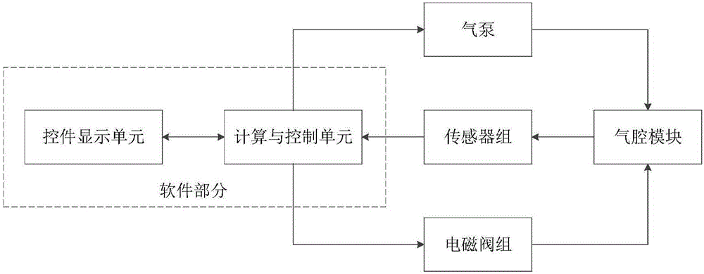
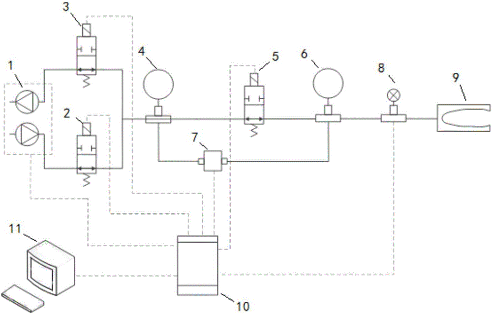
[0044] Such as figure 1 , figure 2 As shown, the pulse wave measurement device designed by the present invention includes software, an air chamber module, an air pump 1, a sensor group, and a solenoid valve group. The air chamber module includes a reference air chamber 4 and a measurement air chamber 5. The elastic bag (finger cuff or wrist cuff) at the measurement site belongs to the measurement air chamber; the air pump 1 realizes the functions of inflation and exhaust; the sensor group includes a gauge pressure sensor 8 and a differential pressure sensor. Sensor 7, wherein the gauge pressure sensor 8 is used for inflation pressure control, and the differential pressure sensor 7 obtains the pulse wave by measuring the differential pressure comparison between the air chamber 6 and the reference air chamber 4; the solenoid valve group includes an inflation solenoid valve 2, an exhaust solenoid valve 3 and the air cavity solenoid valve 5, which respectively control inflation,...


PUM


Abstract

The invention relates to a pulse wave measurement device which comprises a measurement unit and a calculation and control unit (10), wherein the measurement unit comprises a measurement gas cavity (6), a reference gas reference (4), a charging and discharging structure, a differential pressure measurement structure and a pressure measurement structure; the measurement gas cavity (6) comprises an elastic gas bag for monitoring pulse of a measured position; the elastic gas bag is connected with the reference gas cavity (4) by a switchable access; the charging and discharging structure is connected with the measurement gas cavity (6) or the reference gas cavity (4); the differential pressure measurement structure is respectively connected with the measurement gas cavity (6) and the reference gas cavity (4); the pressure measurement structure is connected with the measurement gas cavity (6); the calculation and control unit (10) comprises a controller which is respectively connected with the charging and discharging structure, the differential pressure measurement structure and the pressure measurement structure. Compared with the prior art, according to the pulse wave measurement device disclosed by the invention, a pulse wave is recorded in a differential pressure mode, a differential pressure sensor which further accords with a peripheral vascular pressure variation range is used, a range of the sensor is sufficiently used, and measurement accuracy is improved.

Description

technical field [0001] The invention relates to a device for measuring human physiological characteristics, in particular to a device and method for measuring pulse waves. Background technique [0002] In the process of blood circulation, when the heart contracts and ejects blood, the blood flows through the aorta to the peripheral microvessels, and the volume of the peripheral microvessels becomes larger; when the heart diastole stops ejecting blood, the blood returns from the peripheral microvessels to the heart through the veins, and the volume of the peripheral microvessels increases. get smaller. The volume of peripheral microvessels changes periodically with the heartbeat, which is called volume pulse wave. [0003] Currently, photoplethysmography (PPG) is generally used to measure the volume pulse wave, which is a non-invasive detection method for detecting changes in blood volume in living tissue by means of photoelectric means. On the surface, the transmitted or r...

Claims


Application Information

Patent Timeline
Patent Type & Authority Applications(China)
IPC IPC(8): A61B5/02
CPCA61B5/02A61B5/6824A61B5/6826
Inventor 贾林壮张捷詹航敏叶骞赵振华
Owner 上海中嘉衡泰医疗科技有限公司
Why Eureka
Try Eureka