Nitrogen balance cylinder system for weight balance of machine tool

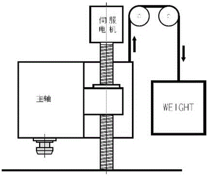
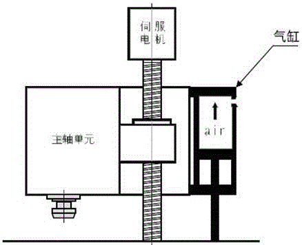
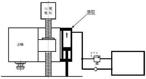
A technology of balance cylinder and nitrogen, which is applied in the direction of maintenance and safety accessories, metal processing machinery parts, metal processing equipment, etc., can solve the problems of heavy load of the lifting drive mechanism, poor response characteristics, rising oil temperature of the hydraulic circuit, etc., and achieve compactness Occupies space, small pressure change, stable balance force effect

Inactive Publication Date: 2017-02-15
JIANGSU ZHISHI TECH CO LTD
View PDF10 Cites 2 Cited by
  • Summary
  • Abstract
  • Description
  • Claims
  • Application Information

AI Technical Summary

Problems solved by technology

The heavy spindle assembly is supported and driven by the lifting drive mechanism. The load on the lifting drive mechanism is heavy, which may reduce the position accuracy of the spindle assembly in the vertical direction, and it is difficult to further increase the lifting speed of the spindle assembly.
In addition, there is also the problem that the lifting drive mechanism supporting the heavy spindle assembly is enlarged and the production cost is high.
[0003] The traditional balancer in the prior art has: as figure 1 The problem of the balancer shown is that the response characteristics are poor, it is not suitable for high-speed cutting, and it takes up a lot of space; figure 2 The cylinder-type balancer shown has the problem that a large-diameter cylinder (easy to cause slipping) is required, a large-capacity air storage container is required, and a large-diameter pneumatic piping is required; image 3 The cylinder type balancer shown has the problem that a hydraulic unit and piping are required, and the oil temperature rise in the hydraulic circuit must be dealt with.

Method used


Image

  • Nitrogen balance cylinder system for weight balance of machine tool
  • Nitrogen balance cylinder system for weight balance of machine tool
  • Nitrogen balance cylinder system for weight balance of machine tool

Examples


Embodiment Construction

[0022] The present invention is described in further detail now in conjunction with accompanying drawing. These drawings are all simplified schematic diagrams, which only illustrate the basic structure of the present invention in a schematic manner, so they only show the configurations related to the present invention.

[0023] The present invention relates to a nitrogen cylinder 1, a controller 2, a nitrogen balancer 3, a ball screw 4, a servo motor 5, a ball screw nut 6, a machine tool spindle 7, a body 8, a connecting block 9, a protection plate 10, a piston rod 11, Technical features such as floating support plate 12, sleeve 13, etc.

[0024] like Figure 4 As shown, a nitrogen gas balancer is used for the spindle assembly of machine tools, and includes a body with a cylinder structure. The top of the body is provided with a gas filling port, and the end of the body is provided with a sleeve. The sleeve is integrally formed with a There is a flange plate with a number of...


PUM


Abstract

The invention discloses a nitrogen balance cylinder system for weight balance of a machine tool. The nitrogen balance cylinder system comprises a nitrogen bottle, a controller and a nitrogen balancer; the controller is arranged on the nitrogen bottle; a servo motor is used for driving a ball screw to rotate so that a ball screw nut can drive a main shaft of the machine tool and the body of the nitrogen balancer to move up and down relative to a piston rod; when the main shaft of the machine tool moves up, the controller is capable of sending an instruction to open a gas charging valve, and the nitrogen bottle is capable of supplying nitrogen into the body of the nitrogen balancer; and when the main shaft of the machine tool moves down, the controller is capable of sending an instruction to close the gas charging valve and open a gas discharging valve. By the nitrogen balance cylinder system disclosed by the invention, the main shaft of the machine tool is more stable when moving up and down, and the servo motor is uniformly loaded when the main shaft of the machine tool moves up and down; the nitrogen balance cylinder system disclosed by the invention is capable of improving the stability of the motion process and improving the machining precision and the surface quality of a product, applicable to high-speed cutting, free of use of a power source and pipes, compact, small in floor space, small in pressure changes and stable in balance force.

Description

technical field [0001] The invention relates to a balance device, in particular to a nitrogen balance cylinder system used for counterweights of machine tools. Background technique [0002] A machine tool such as a machining center is provided with a main shaft and a main shaft assembly having an electric motor for rotationally driving the main shaft, and the main shaft assembly is supported and driven up and down by an elevating drive mechanism. This lifting drive mechanism is usually a ball screw, a ball nut screwed with the ball screw and connected to the main shaft assembly, and an electric motor, and the main shaft assembly and the ball nut are driven up and down together by the electric motor rotating the ball screw. . The heavy spindle assembly is supported and driven by the lifting drive mechanism. The load of the lifting drive mechanism is heavy, which may reduce the positional accuracy of the spindle assembly in the vertical direction, and it is difficult to furth...

Claims


Application Information

Patent Timeline
Patent Type & Authority Applications(China)
IPC IPC(8): B23Q11/00
CPCB23Q11/0017
Inventor 范磊
Owner JIANGSU ZHISHI TECH CO LTD
Why Eureka
Try Eureka