Water purification system and control method thereof

A water purification system and control method technology, applied in water treatment parameter control, chemical instruments and methods, multi-stage water treatment, etc. Effect

Active Publication Date: 2017-02-15
GREE ELECTRIC APPLIANCES INC
View PDF2 Cites 17 Cited by
  • Summary
  • Abstract
  • Description
  • Claims
  • Application Information

AI Technical Summary

Problems solved by technology

[0003] Based on this, it is necessary to provide a water purification system and its control method for the unreasonable use of reverse osmosis membranes in traditional water purification systems

Method used


Image

  • Water purification system and control method thereof
  • Water purification system and control method thereof
  • Water purification system and control method thereof

Examples


Embodiment 2

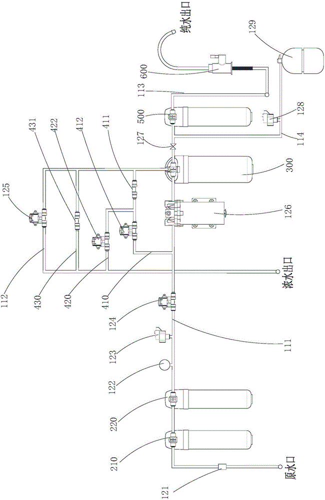
[0116] see figure 2 As shown, the difference between Embodiment 2 of the present invention and Embodiment 1 is that the concentrated water discharge control unit also includes a third branch 430, and the water inlet end of the third branch 430 is connected to the concentrated water outlet of the reverse osmosis membrane treatment unit 300. On the concentrated water pipeline 112 between the concentrated water discharge solenoid valve 125, the water outlet end of the third branch 430 is connected to the water outlet section of the concentrated water pipeline 112 or directly emptied, and the third branch 430 is provided with a third Wastewater ratio 431.

[0117] Correspondingly, the control method of the above-mentioned water purification system provided by the present invention is different from Embodiment 1 in that:

[0118] S200: When the water purification system produces water, control the concentrated water discharge control unit to cycle between the first operation mode...

Embodiment 3

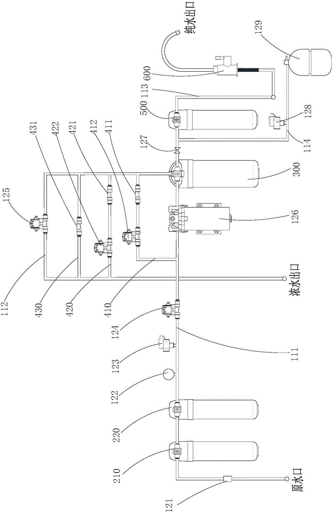
[0128] see image 3 As shown, the difference between the third embodiment of the present invention and the second embodiment is that the wastewater ratio component of the concentrated water discharge control unit also includes a second wastewater ratio 421 .

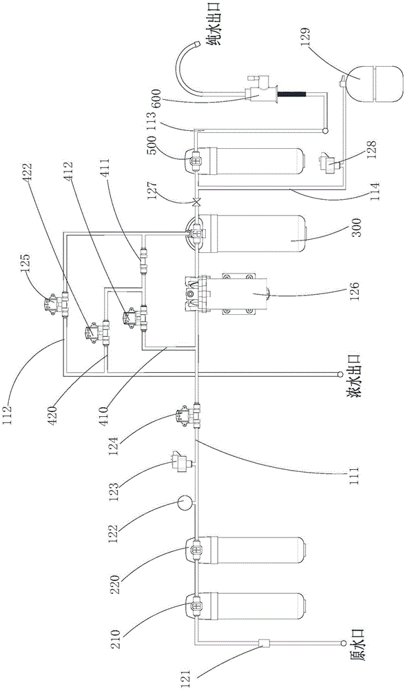
[0129] The water inlet end of the first branch 410 is connected to the water outlet end of the first waste water ratio 411, and the water inlet end of the first waste water ratio 411 is connected to the outlet between the concentrated water outlet of the reverse osmosis membrane treatment unit 300 and the concentrated water discharge solenoid valve 125. On the concentrated water pipeline 112; the water inlet end of the second branch 420 is connected to the water outlet end of the second waste water ratio 421, and the water inlet end of the second waste water ratio 421 is connected to the concentrated water outlet of the reverse osmosis membrane treatment unit 300 and the concentrated water discharge On the concentrated w...


PUM


Abstract

The invention provides a water purification system which comprises a concentrated water emission control unit, wherein the concentrated water emission control unit comprises a first branch, a second branch and a wastewater ratio assembly; a water outlet end of the first branch is connected with a water inlet pipeline; the first branch is provided with a first electromagnetic valve; a water outlet end of the second branch is connected with a water outlet section of a concentrated water pipeline or is directly evacuated; the second branch is provided with a second electromagnetic valve; and a water inlet end of the first branch and a water inlet end of the second branch are connected to a concentrated water pipeline between a concentrated water outlet of a reverse osmosis membrane treatment unit and a concentrated water emission electromagnetic valve through the wastewater ratio assembly. The first electromagnetic valve on the first branch and the second electromagnetic valve on the second branch are controlled to open and close intermittently, thereby implementing concentrated water intermittent reflux, reducing the concentrated water emission, and enhancing the recovery rate of the water purification system. The concentrated water reflux is intermittent and controllable, thereby greatly lowering the reverse osmosis membrane pressure and avoiding the shortening of the service life.

Description

technical field [0001] The invention relates to the technical field of water purification, in particular to a water purification system and a control method thereof. Background technique [0002] The traditional water purification system has the disadvantages of low recovery rate and large discharge of concentrated water. In order to realize the water-saving effect of the water purification system, the water purification system with high recovery rate generally adopts the process of reducing concentrated water discharge or returning the concentrated water to improve the recovery rate. Although these two water treatment processes have improved the recovery rate to a certain extent rate, to achieve the purpose of water saving, but directly reduce the discharge of concentrated water or return all the concentrated water, the reverse osmosis membrane surface will produce serious concentration polarization, if the reverse osmosis membrane surface can not be disturbed in time CaCO ...

Claims


Application Information

Patent Timeline
Patent Type & Authority Applications(China)
IPC IPC(8): C02F9/02
CPCC02F9/00C02F1/001C02F2209/001C02F2209/03C02F2209/10C02F1/441C02F2301/08C02F2303/16Y02A20/131
Inventor 张细燕胡进华李一然秦利利许鹏周栋周平发林治权杨勇
Owner GREE ELECTRIC APPLIANCES INC
Why Eureka
Try Eureka