Cell capturing chip based on inductive charge electro-osmosis induced by rotating electric field

A technology of induced electric charge and rotating electric field, applied in the methods of stress-stimulated microbial growth, biochemical instruments, biochemical equipment and methods, etc., can solve the problem of unsuitable capture of Joule heat and other problems, and achieve efficient single capture, low conductivity, Low voltage effect

Inactive Publication Date: 2017-02-15
HARBIN INST OF TECH
View PDF5 Cites 17 Cited by
  • Summary
  • Abstract
  • Description
  • Claims
  • Application Information

AI Technical Summary

Problems solved by technology

[0004] The purpose of the present invention is to solve the problem that the dielectrophoretic capture method is not suitable for capturing small cells and e

Method used


Image

  • Cell capturing chip based on inductive charge electro-osmosis induced by rotating electric field
  • Cell capturing chip based on inductive charge electro-osmosis induced by rotating electric field
  • Cell capturing chip based on inductive charge electro-osmosis induced by rotating electric field

Examples


specific Embodiment approach 1

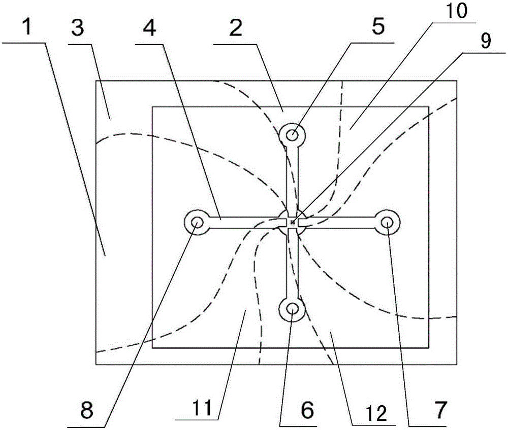
[0015] Specific implementation mode one: combine figure 1 To illustrate this embodiment, a cell capture chip based on induced charge electroosmosis induced by a rotating electric field described in this embodiment includes a glass substrate 1, a PDMS cover 2, a first excitation electrode 3, a second excitation electrode 10, a third The excitation electrode 11, the fourth excitation electrode 12 and the suspension electrode array 9;

[0016] The PDMS cover 2 is fixed on the glass substrate 1, and the glass substrate 1 is used to carry the PDMS cover 2, the first excitation electrode 3, the second excitation electrode 10, the third excitation electrode 11, the fourth excitation electrode 12 and the suspension electrode Array 9; two mutually perpendicular PDMS channels 4 are opened on the PDMS cover sheet 2; one end of a PDMS channel is provided with a main channel inlet 5, and the main channel inlet 5 is used to inject a solution containing a single cell, and the other end is pr...

specific Embodiment approach 2

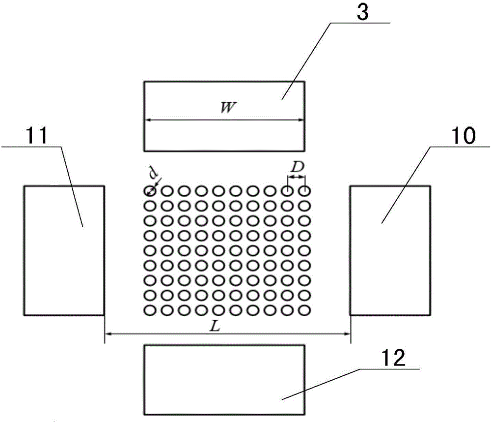
[0021] Specific implementation mode two: combination figure 2 and image 3 Describe this embodiment, this embodiment is to further limit the cell capture chip based on the induced charge electroosmosis induced by the rotating electric field described in the first embodiment, in this embodiment, the suspension electrode array 9 includes N× N floating electrodes, N×N floating electrodes are arranged in N rows and N columns, and the floating electrode array 9 is a square;

[0022] Said N is an integer greater than 3.

[0023] In this embodiment, if figure 2 As shown, the suspension electrode is a cylinder, the diameter d of the cylinder is 20 μm, and the distance D between two cylinders adjacent to each other in the same row or column is 40 μm.

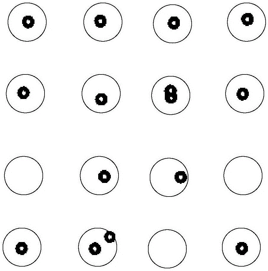
[0024] During the experiment of capturing cells, first, add a certain amount of deionized water to the beaker, slowly add potassium chloride, and monitor the conductivity of the solution in real time with a conductivity meter to obt...

specific Embodiment approach 3

[0032] Specific embodiment three: this embodiment further defines the cell capture chip based on the induced charge electroosmosis induced by the rotating electric field described in the second specific embodiment. In this embodiment, the inner part of the first excitation electrode 3 The distance between the end and the inner end of the fourth exciting electrode 12 is greater than the side length of the suspended square floating electrode array 9, and the distance between the inner end of the second exciting electrode 10 and the inner end of the third exciting electrode 11 is greater than the square floating electrode array. The side length of the electrode array 9 is to ensure that the F solution can pass through the PDMS channel 4 normally.

[0033] In this embodiment, the distance between the inner end of the first excitation electrode 3 and the inner end of the fourth excitation electrode 12 is equal to the distance between the inner end of the second excitation electrode ...


PUM

PropertyMeasurementUnit
The inside diameter ofaaaaaaaaaa

Abstract

The invention discloses a cell capturing chip based on inductive charge electro-osmosis induced by a rotating electric field, and relates to a micro-fluidic chip based on inductive charge electro-osmosis induced by the rotating electric field. The invention aims to solve the problem that a dielectrophoresis capturing method is not suitable for capturing small cell and joule heat is easily generated in capturing the cell. A PDMS (polydimethylsiloxane) cover plate is fixed on a glass substrate, and two PDMS channels perpendicular to each other are arranged on the PDMS cover plate; both ends of two PDMS channels are respectively provided with a main channel inlet, a main channel outlet, a secondary channel inlet and a secondary channel outlet; a suspension electrode array is placed at an intersection of the PDMS; an inner end part of a first exciting electrode, an inner end part of a second exciting electrode, an inner end part of a third exciting electrode and an inner end part of a fourth exciting electrode are respectively located at four different directions of the suspension electrode array. The invention has the beneficial effects that the cell capturing chip is small in captured cell size, high in capturing efficiency, and is not easy to generate joule heat. The cell capturing chip based on the vortex of the flow field is applicable to capture cells with different sizes.

Description

technical field [0001] The invention relates to a microfluidic chip based on induction charge electroosmosis induced by electric field temptation. Background technique [0002] Cells are the basic unit of dough. In order to better understand the related issues of biochemistry and genetic inheritance, it is often necessary to culture and analyze a large number of cells in petri dishes or complex bioreactors. In analysis, however, the behavior of individual cells is hidden from the complex interplay between the reactor environment and cellular activity. Therefore, the capture and detection of individual cells or particles can not only better understand and analyze the behavior of individual cells, but also have extremely important values ​​in the fields of genetic inheritance and metabolic engineering. [0003] Among the current methods for operating and analyzing individual cell behaviors, fluorescence-activated cell sorting technology can perform high-throughput screening ...

Claims


Application Information

Patent Timeline
IPC IPC(8): C12M1/42G01N15/10
CPCC12M47/04G01N15/10
Inventor 姜洪源任玉坤吴玉潘
Owner HARBIN INST OF TECH
Why Eureka
Try Eureka