Magnetic Bionic Blade Rotor in Heat Exchange Tubes

A blade rotor and heat exchange tube technology, which is applied in the field of magnetic bionic blade rotor, can solve the problems of enhanced heat transfer and scale prevention and descaling capabilities, the effect of field synergy enhanced heat transfer is not significant, and the reduction of fluid flow resistance in the tube is achieved. Improve and strengthen the heat transfer capacity, good turbulence effect, and improve the effect of operating efficiency

Active Publication Date: 2018-06-26
BEIJING UNIV OF CHEM TECH
View PDF9 Cites 0 Cited by
  • Summary
  • Abstract
  • Description
  • Claims
  • Application Information

AI Technical Summary

Problems solved by technology

To sum up, the spiral bond has the following main disadvantages: (1) The bond is a whole, which directly scratches the heat transfer tube and damages the inner wall of the heat transfer tube; (2) When the fluid flows to push the bond to rotate, it requires a large driving torque and consumes more (3) The service life of the bearing used for single-end fixing is short; (4) The effect of field synergy enhanced heat transfer generated by the bond is not significant
But the disadvantage is that when a certain fluid passes through, the rotation speed of the rotor is determined by the helix angle of the flight. When the flight lead is small, the rotation speed of the rotor is fast, and the resistance to the fluid increases accordingly; in order to solve this problem , China Patent Application No. 200910077378.0, the title of the invention is "A Unit Combined Enhanced Heat Transfer Device". The device is composed of a rotor, a support frame, a sleeve shaft and a connecting axis. The two ends of the tube are respectively fixed on the support frame, and multiple rotors are mounted on the connecting axis. The rotor is composed of a spoiler blade, a hinge structure, and a tail screw drive blade. This structure can significantly reduce the flow resistance of the fluid in the tube. , reduce wear and prolong the service life of the rotor, but the enhanced heat transfer and anti-scaling and descaling capabilities of the rotor with this structure are limited to a certain extent

Method used


Image

  • Magnetic Bionic Blade Rotor in Heat Exchange Tubes
  • Magnetic Bionic Blade Rotor in Heat Exchange Tubes

Examples


Embodiment Construction

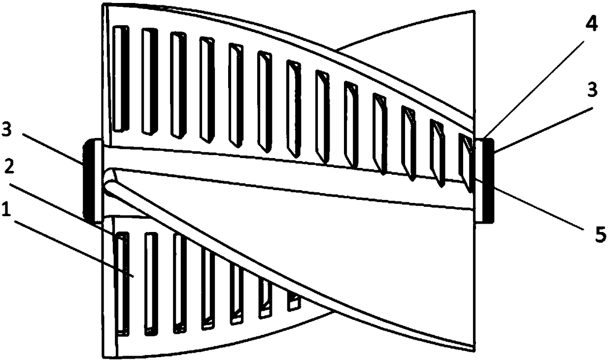
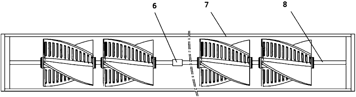
[0016] Such as figure 2 As shown, the present invention relates to an implementation method of a magnetic bionic blade rotor in a heat exchange tube. The enhanced heat transfer device includes a rotor, a limiting member 6, a heat exchange tube 7, and a rotating shaft 8. Several rotors are connected in series through the rotating shaft 8. Together, the limiting member 6 divides the plurality of rotors into several groups of rotor strings, which are fixed on both ends of the heat exchange tube 7, and the two ends of the rotating shaft 8 are respectively fixed on the heat exchange tube 7. The rotor of the present invention is composed of a certain number of bionic The blade 1 is fixed on the surface of the hollow shaft 4, and the surface of the bionic blade is provided with a rectangular opening 2 and a reverse spiral small blade 5 on the opening. Among the two adjacent rotors, the magnet 3 at the head of the hollow shaft 4 of one rotor is combined with the magnet 3 at the tail ...


PUM


Abstract

The invention aims at designing rotors of a novel structure. Rectangular open hole structures are arranged on the surfaces of blades of the rotors; spiral small blade structures opposite to the overall direction of the blades are arranged at rectangular open holes; and meanwhile, magnets are attached to the two ends of a hollow shaft of each rotor. According to the rotors of the structure, the frictional resistance between the adjacent rotors is obviously reduced, and the fluid resistance is reduced; meanwhile, the strengthened heat transfer performance and the self-cleaning performance of the rotors are not reduced; and the strengthened heat exchange performance and the descaling performance of the rotors can be further improved.

Description

technical field [0001] The invention relates to an interpolation element for enhancing heat transfer and anti-fouling and decontamination in heat exchange tubes used in shell-and-tube heat exchangers, heat exchange reactors and other equipment, in particular to an interpolation element that uses the heat transfer fluid inside the heat exchange tube as the Power, low energy consumption and high efficiency magnetic bionic (shark gills) blade rotor that realizes self-cleaning and enhanced heat transfer function. Background technique [0002] Energy saving and emission reduction is a key technology that the whole world attaches great importance to. It is applied to many heat exchangers in many fields such as petroleum, chemical industry, thermal power, nuclear power, metallurgy, light industry, aviation devices and marine vehicles, among which the most Shell-and-tube heat exchangers are widely used, but there are common problems of fouling and fouling in the inner walls of these...

Claims


Application Information

Patent Timeline
Patent Type & Authority Patents(China)
IPC IPC(8): F28F13/12F28F19/00F28G3/10
CPCF28F13/125F28F19/002F28F2250/08F28G3/10
Inventor 阎华杨优生丁玉梅关昌峰杨卫民
Owner BEIJING UNIV OF CHEM TECH
Why Eureka
Try Eureka