Grid protection circuit and power electronic equipment

A technology for protecting circuits and gates, applied in the direction of high-efficiency power electronic conversion, electronic switches, electrical components, etc., can solve the problems of affecting switching speed, unreasonable, and increasing the charge of MOSFET, so as to improve reliability and reduce gate overshoot. Voltage failure, the effect of optimizing MOSFET parameters

Inactive Publication Date: 2017-02-15
MIDEA GRP CO LTD +1
View PDF5 Cites 5 Cited by
  • Summary
  • Abstract
  • Description
  • Claims
  • Application Information

AI Technical Summary

Problems solved by technology

[0005] However, under the same withstand voltage load, the parasitic capacitance of MOSFET with wide bandgap material is much smaller than that of semiconductor device made of silicon material, which is more sensitive to the parasitic parameters of the driving circuit, and is more suitable for working at the driving voltage of -2 ~ +20V. Silicon material semiconductor devices are suitable to work under the driving voltage of 0-15V, and the voltage U GS (the voltage between the gate and source) goes negative, the oxide capacitance across the gate-source increases, which increases the amount of charge required to turn the MOSFET on and off, affecting switching speed
Therefore, it is unreasonable to completely apply the driving method of silicon material semiconductor devices to drive wide bandgap material MOSFETs.

Method used


Image

  • Grid protection circuit and power electronic equipment
  • Grid protection circuit and power electronic equipment
  • Grid protection circuit and power electronic equipment

Examples


Embodiment Construction

[0038] In order to understand the above-mentioned purpose, features and advantages of the present invention more clearly, the present invention will be further described in detail below in conjunction with the accompanying drawings and specific embodiments. It should be noted that, in the case of no conflict, the embodiments of the present application and the features in the embodiments can be combined with each other.

[0039] In the following description, many specific details are set forth in order to fully understand the present invention. However, the present invention can also be implemented in other ways different from those described here. Therefore, the protection scope of the present invention is not limited by the specific details disclosed below. EXAMPLE LIMITATIONS.

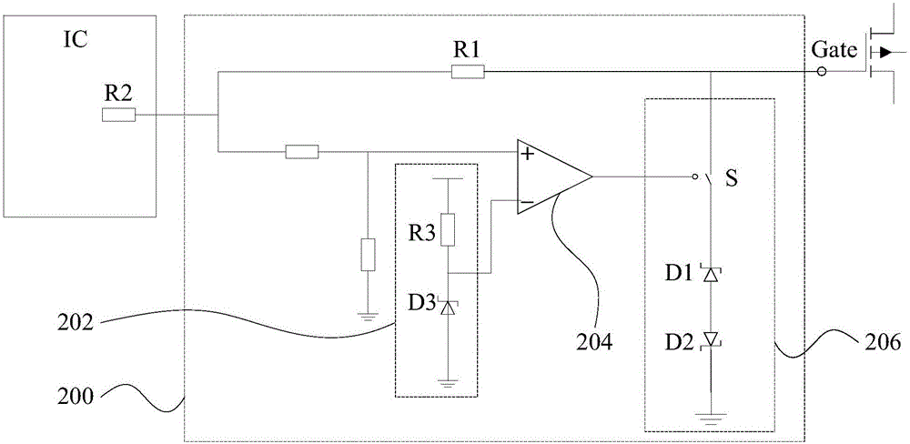
[0040] figure 2 A schematic diagram of a gate protection circuit according to an embodiment of the present invention is shown.

[0041] Such as figure 2 As shown, the gate protection circuit 200...


PUM


Abstract

The invention provides a grid protection circuit and power electronic equipment. The grid protection circuit comprises a main transmission line, a reference module, a comparison module, and a voltage stabilization module, wherein the main transmission line is connected between a grid driving module and the grid of an MOS transistor; the reference module is used for generating a reference signal; two input ends of the comparison module are respectively connected with the grid driving module and the reference module for comparing a grid driving signal and the reference signal; and the voltage stabilization module is connected between the output end of the main transmission line and the ground wire, and the driving end of the voltage stabilization module is connected with the output end of the comparison module. When the grid driving signal is larger than or equal to the reference signal, the comparison module outputs an on signal to the voltage stabilization module to control the voltage stabilization module to be on, the voltage stabilization module outputs a clamp voltage signal to the grid of the MOS transistor, and the clamp voltage signal is smaller than the grid driving signal. Through the technical scheme of the invention, the reliability and the accuracy of over current protection are enhanced.

Description

technical field [0001] The present invention relates to the technical field of grid protection circuits, in particular to a grid protection circuit and a power electronic device. Background technique [0002] Intelligent Power Module, or IPM (Intelligent Power Module), is a power drive device (Deriver Integrated Circuit, or Driver IC) that combines power electronics and integrated circuit technology. Due to the advantages of high integration and high reliability, intelligent power modules are winning more and more markets, especially suitable for frequency converters and various inverter power supplies for driving motors, and are ideal for frequency control, metallurgical machinery, electric traction, servo Power electronic devices commonly used in driving and frequency conversion household appliances. [0003] Wide bandgap materials represented by silicon carbide and gallium nitride are applied to semiconductor devices, especially in the driver IC (Deriver Integrated Circu...

Claims


Application Information

Patent Timeline
Patent Type & Authority Applications(China)
IPC IPC(8): H02M1/32H03K17/08
CPCH02M1/32H03K17/08H03K2017/0806Y02B70/10
Inventor 刘东子冯宇翔
Owner MIDEA GRP CO LTD
Why Eureka
Try Eureka