Tin-powder ultrasonic atomization device and atomization process thereof

A technology of atomizing tin powder and ultrasonic wave, which is applied in the field of ultrasonic atomizing tin powder device and its atomization process, can solve the problems of secondary damage, oxide layer damage, oxygen content fluctuation, etc., and achieve high product precision and guarantee uniformity , the effect of high sphericity

Inactive Publication Date: 2017-02-22
GUANGDONG TIANGAO TECH CO LTD
View PDF0 Cites 9 Cited by
  • Summary
  • Abstract
  • Description
  • Claims
  • Application Information

AI Technical Summary

Problems solved by technology

Because the working principle of centrifugal atomization is to rely on centrifugal force to throw out the solution and form a spherical shape in the air, the sphericity of the tin powder formed in the air will be limited by the cooling temperature and unstable factors such as the process, resulting in insufficient sphericity of the powder. It has an impact on the passability of SMT high-precision printing in the later stage
In addition, because centrifugal atomization requires a larger space for cooling, the larger the tank space, the more difficult it is to control the oxygen content in the gas to achieve uniform control, so the stability of the oxygen content on the surface of the powder is not enough, and the fluctuation of the oxygen content is relatively large , the powder oxygen content characteristics are not stable enough
[0004] In addition, for the centrifugal atomization process, most of the fine powder exceeds the qualified requirements, which will cause more difficulty in the later screening and separation, and it is difficult to ensure the uniformity of particle size. It is necessary to install a dust treatment device to remove the fine powder, but During this process, the friction of the pipeline will cause secondary damage to the surface of the qualified product, including the damage of the sphericity and the damage of the oxide layer after the surface collision

Method used


Image

  • Tin-powder ultrasonic atomization device and atomization process thereof
  • Tin-powder ultrasonic atomization device and atomization process thereof

Examples


Embodiment 1

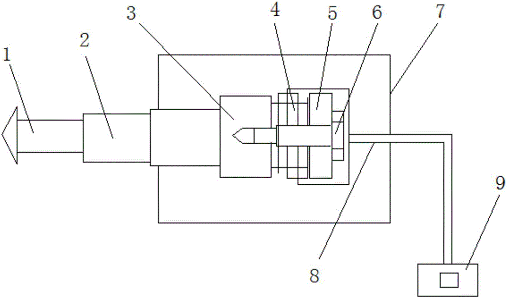
[0030] An ultrasonic atomization tin powder device, including a tool head 1, a horn 2 is provided on one side of the tool head 1, a cooling device 7 is provided on one side of the horn 2, and a cooling device 7 is located in the cooling device 7 One end of the rod 2 is provided with a transducer front cover 3, and one side of the transducer front cover 3 is provided with a transducer rear cover 5, and a press is provided between the transducer front cover 3 and the transducer rear cover 5. Electroceramic stack 4 , one side of the cooling device 7 is provided with an electrode lead 8 electrically connected to the piezoelectric ceramic stack 4 , and a signal generator 9 is provided at one end of the electrode lead 8 . One side of the transducer back cover 5 is provided with a prestressed bolt 6 threadedly connected to the transducer back cover 3 . The cross-sectional area of ​​the transducer front cover 3 and the transducer rear cover 5 is the same.

[0031] The present inventi...

Embodiment 2

[0040] An ultrasonic atomization tin powder device, including a tool head 1, a horn 2 is provided on one side of the tool head 1, a cooling device 7 is provided on one side of the horn 2, and a cooling device 7 is located in the cooling device 7 One end of the rod 2 is provided with a transducer front cover 3, and one side of the transducer front cover 3 is provided with a transducer front cover 5, and a press is provided between the transducer front cover 3 and the transducer rear cover 5. Electroceramic stack 4 , one side of the cooling device 7 is provided with an electrode lead 8 electrically connected to the piezoelectric ceramic stack 4 , and a signal generator 9 is provided at one end of the electrode lead 8 . One side of the transducer back cover 5 is provided with a prestressed bolt 6 threadedly connected to the transducer back cover 3 . The cross-sectional area of ​​the transducer front cover 3 and the transducer rear cover 5 is the same.

[0041] The present invent...

Embodiment 3

[0050] An ultrasonic atomization tin powder device, including a tool head 1, a horn 2 is provided on one side of the tool head 1, a cooling device 7 is provided on one side of the horn 2, and a cooling device 7 is located in the cooling device 7 One end of the rod 2 is provided with a transducer front cover 3, and one side of the transducer front cover 3 is provided with a transducer rear cover 5, and a press is provided between the transducer front cover 3 and the transducer rear cover 5. Electroceramic stack 4 , one side of the cooling device 7 is provided with an electrode lead 8 electrically connected to the piezoelectric ceramic stack 4 , and a signal generator 9 is provided at one end of the electrode lead 8 . One side of the transducer back cover 5 is provided with a prestressed bolt 6 threadedly connected to the transducer back cover 3 . The cross-sectional area of ​​the transducer front cover 3 and the transducer rear cover 5 is the same.

[0051] The present inventi...


PUM


Abstract

The invention discloses a tin-powder ultrasonic atomization device. The tin-powder ultrasonic atomization device comprises a tool head, wherein an amplitude varying pole is arranged on one side of the tool head, a cooling device is arranged on one side of the amplitude varying pole, a transducer front cover is arranged at the part, in the cooling device and located at one end of the amplitude varying pole, a transducer rear cover is arranged on one side of the transducer front cover, a piezoelectric ceramic stack is arranged between the transducer front cover and the transducer rear cover, an electrode lead electrically connected to the piezoelectric ceramic stack is arranged on one side of the cooling device, and a signal generator is arranged at one end of the electrode lead. Ultrasonic atomization of tin powder researched and developed by the invention can fundamentally solve the defects, ultrasonic is formed according to liquid surface tension waves to generate atomization, namely liquid metal forms a liquid film on the surface of an atomization head under ultrasonic vibration, and then the liquid film is broken by the effect of the vibration, uniform spheres are separated from the liquid film and formed, so that the sphericity of the generated powder is higher.

Description

technical field [0001] The invention relates to the technical field of atomized tin powder, in particular to an ultrasonic atomized tin powder device and an atomization process thereof. Background technique [0002] Tin is currently one of the highly developed and utilized minerals among nonferrous metals in my country, and is widely used in metallurgy, electronics, electrical appliances, chemicals, building materials, machinery and food packaging and other industries. With the continuous development of lead-free trend on a global scale, electronic product manufacturers will apply more tin powder materials to their products. At the same time, with the increasing awareness of environmental protection, the non-toxic and environmentally friendly properties of tin powder will enable it to be continuously applied to packaging fields such as medicine, chemical industry, light industry, food, health care, and art supplies in the future. The importance of tin powder has become more...

Claims


Application Information

Patent Timeline
Patent Type & Authority Applications(China)
IPC IPC(8): B22F9/08
CPCB22F9/08B22F2009/0808
Inventor 张锦镜
Owner GUANGDONG TIANGAO TECH CO LTD
Why Eureka
Try Eureka