
34CrNiMo6 wind power main shaft forging forming method for low wind speed wind turbine set

A technology for wind power spindles and wind turbines, which is used in engine manufacturing, mechanical equipment, engine components, etc., can solve the problems of overheating of the small diameter end, easy overcooling of the small diameter end, and large size of the wind power spindle, so as to improve the mechanical performance and reduce the The effects of unbalanced tissue

Inactive Publication Date: 2017-02-22
JIANGSU JINYUAN FORGE
View PDF6 Cites 5 Cited by
  • Summary
  • Abstract
  • Description
  • Claims
  • Application Information

AI Technical Summary

Problems solved by technology

Using traditional forging and heat treatment methods, due to the large size of the wind power main shaft, the segregation of the billet obtained by ordinary electric furnace smelting is serious, and it is difficult to improve it in the subsequent forging process. When cooling, it is often easy to cause the small diameter end to overheat, and when cooling, the small diameter end is easy to overheat
In addition, the wind power main shaft is in a state of perennial operation, which has high requirements for its various mechanical properties, and the existing heat treatment process: normal tempering + quenching and tempering, cannot meet its high performance requirements. Therefore, many The main shafts of wind power enterprises are all imported from abroad

Method used


Image

  • 34CrNiMo6 wind power main shaft forging forming method for low wind speed wind turbine set
  • 34CrNiMo6 wind power main shaft forging forming method for low wind speed wind turbine set

Examples


Embodiment Construction

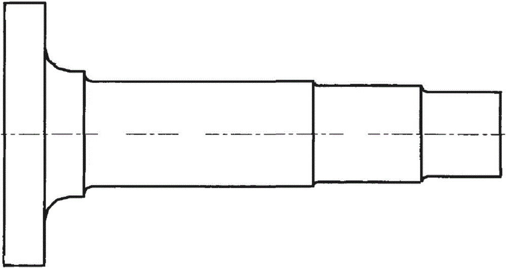
[0046] Such as Figure 1-2 Shown is a forging method for a 34CrNiMo6 wind power main shaft of a low wind speed wind turbine. The wind power main shaft includes a flange part and a variable-section shaft part.

[0047]The composition of the 34CrNiMo6 wind power main shaft material of the low wind speed wind turbine is controlled as follows: C0.30%~0.37%, Si 0.30%~0.60%, Mn 0.60%~1.00%, Cr 1.40%~1.70%, Ni 1.40%~1.70% , Mo 0.15%~0.35%, P<0.008%, S<0.005%, Cu<0.05%, As<0.005%, Al<0.005%, Sn<0.005%, Sb<0.005%, the rest is Fe and unavoidable Impurities.

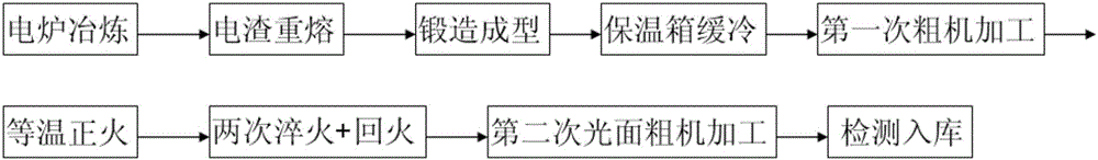
[0048] The 34CrNiMo6 wind power spindle forging method of the low wind speed wind turbine specifically includes the following steps:

[0049] Step a, select steel ingot raw materials smelted by electric furnace + LF (outside furnace refining) + VD (vacuum degassing) + vacuum casting;

[0050] Step b, electroslag remelting the steel ingot raw material in step a;

[0051] Step c, pre-forging billet: heating the electroslag remelt...


PUM


Abstract

The invention discloses a 34CrNiMo6 wind power main shaft forging forming method for a low wind speed wind turbine set. The method includes the step a of adopting of electric furnace smelting, secondary refining, vacuum gas removing and vacuum steel ingot raw material casting and smelting; the step b of electro-slag remelting of a steel ingot raw material in the step a; the step c of pre-forging for blank manufacturing; the step d of final forging forming; the step e of slow cooling of a heat-preserving box; the step f of first-time rough machining, and ultrasonic non-destructive detection; the step g of isothermal normalizing for preparing heat treatment; the step h of two times of quenching and tempering final heat treatment; and the step i of detection for qualification and packaging and warehousing. By means of the 34CrNiMo6 wind power main shaft forging forming method for the low wind speed wind turbine set, the structure property of the flange portion of a wind power main shaft and the variable cross-section shaft portion is made to be uniform, and the mechanical performance of the 34CrNiMo6 wind power main shaft of the low wind speed wind turbine set is greatly improved.

Description

technical field [0001] The patent of the present invention relates to a forging forming method of shaft parts, specifically, a forging forming method of a 34CrNiMo6 wind power main shaft of a low wind speed wind turbine. Background technique [0002] Energy is the basic driving force for economic and social development. The energy industry is facing the dual pressure of economic growth and environmental protection. The development and utilization of renewable energy is the basic choice for global energy development in the 21st century. Wind energy is the most economically utilized and Industrialized development of valuable clean renewable energy. [0003] The wind turbine is the core equipment of the wind farm. In the construction investment of the wind farm, the wind turbine equipment fee is the main part of the wind power project investment, accounting for about 60%-80% of the total investment. The main components of the wind turbine include: blades, control System, gener...

Claims


Application Information

Patent Timeline
IPC IPC(8): B23P15/00
CPCB23P15/00F05B2230/21F05B2230/40
Inventor 葛艳明袁志伟蒋志强
Owner JIANGSU JINYUAN FORGE
Learn More