A hollow cup motor rotor polishing device

A technology of motor rotor and polishing device, which is applied in the direction of grinding/polishing equipment, parts of grinding machine tools, grinding feed movement, etc., which can solve the operation risks and constraints of occupying the operator's operating time and increasing the mechanical injury of the operator Coreless motor manufacturing cost and other issues

Active Publication Date: 2018-05-29
ONCE TOP MOTOR MFG
View PDF5 Cites 0 Cited by
  • Summary
  • Abstract
  • Description
  • Claims
  • Application Information

AI Technical Summary

Problems solved by technology

Manual operation to complete the above operations will take up the operating time of the operator, which restricts the production cost of the coreless motor
In addition, since the slewing device has a certain speed, manual operation will also increase the risk of mechanical injury to the operator

Method used


Image

  • A hollow cup motor rotor polishing device
  • A hollow cup motor rotor polishing device
  • A hollow cup motor rotor polishing device

Examples


Embodiment 1

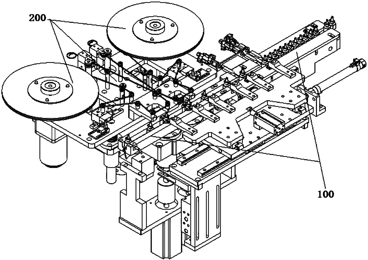
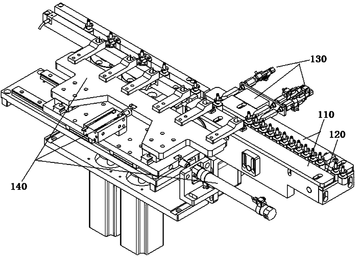
[0039] Such as figure 2 As shown, the present invention provides a hollow cup motor rotor polishing device, including: an automatic feeding device 100 and an automatic polishing device 200; image 3 and Figure 4 As shown, the automatic feeding device 100 includes: a track groove 110, a conveyor belt 120, a material level positioning device 130 and a material shifting device 140; the track groove 110 is composed of two parallel guide plates, and the conveyor belt 120 is arranged directly below the track groove 110; the material level positioning device 130 includes several actuator cylinders 131 fixed on one side of the track groove, and the action end is fixed with a blocking block 132; the blocking block 132 has a degree of freedom of movement for blocking the material running in the track groove; the material shifting device 140 includes: a shifting disc 141 provided with several shift forks 142, and driving the shifting disc 141 in contact with the The tray driving devi...

Embodiment 2

[0045] Figure 10 As shown, in this embodiment, on the basis of Embodiment 1, the base plate 221 is provided with a polishing tape automatic feeding device 240; the polishing tape automatic feeding device includes: a polishing tape feeding tray 241, a polishing tape guide wheel 242 and a polishing tape Belt receiving device 243; the base plate is fixed with a rotary shaft 244, the rotary shaft 244 is provided with the polishing tape material tray 241; the polishing tape receiving device 243 is provided with a polishing tape receiving gear 245 and The polishing belt receiving gear stepping motor 246 that drives the polishing belt receiving gear 245 to rotate; the polishing belt 223 is guided by the polishing belt guide wheel 242 after being drawn out from the polishing belt material tray 241 to the Polishing belt receiving device 243; the output end of the polishing belt receiving gear stepping motor 246 is fixedly provided with a driving gear 247 meshing with the polishing bel...


PUM


Abstract

The invention discloses a polishing device for a hollow cup motor rotor. The polishing device has the technical advantages of simple structure, convenience in maintenance and high operation efficiency. The structure of the polishing device comprises an automatic feeding device and an automatic polishing device, wherein the automatic feeding device comprises a rail slot, a conveyer belt, a material level positioning device and a material stirring device; the material stirring device comprises a material stirring plate and a material plate driving device; the material stirring plate is equipped with a plurality of stirring forks; the material plate driving device is used for driving the material stirring plate to traverse on a plane as high as the plane of the rail slot; the automatic polishing device comprises a material rotation driving device, a polishing belt feeding device and a polishing executing device for driving the polishing belt feeding device to advance and retreat; the polishing belt feeding device comprises a base plate and a polishing belt; the base plate is equipped with a station slot; the polishing belt is arranged above the station slot. The polishing device provided by the invention can automatically polish the hollow cup motor rotor located in an automatic production line of the hollow cup motor rotor.

Description

technical field [0001] The invention relates to the technical field of hollow cup motor automatic manufacturing equipment, in particular to a hollow cup motor rotor polishing device. Background technique [0002] The coreless motor belongs to the DC permanent magnet, servo micro motor. The main difference from the ordinary motor is the ironless rotor, also called the coreless rotor. The stator is magnet steel inside. figure 1 The structure of the coreless motor in the prior art shown includes: a rear cover 1, a brush holder 2, a coreless rotor 3, a gasket 4, a NdFeB magnet 5, a stator 6, a bearing 7, and a retaining spring 8 . Coreless motors have very prominent energy-saving, control and drag characteristics, mainly including: 1. Energy-saving characteristics: energy conversion efficiency is very high, and its maximum efficiency is generally above 70%, and some products can reach above 90% (iron-core motors generally at 20-50%). 2. Control characteristics: fast starting...

Claims


Application Information

Patent Timeline
Patent Type & Authority Patents(China)
IPC IPC(8): B24B21/00B24B21/02B24B21/18B24B41/00
CPCB24B21/004B24B21/02B24B21/18B24B41/005
Inventor 张用万
Owner ONCE TOP MOTOR MFG
Why Eureka
Try Eureka