Delayed coking method and apparatus for heavy oil

A delayed coking and heavy oil technology, applied in cracking, petroleum industry, non-catalytic thermal cracking, etc., can solve the problems of not reducing the water injection of coking furnace, increasing the heat load of heating furnace, and coking of heating furnace tube, so as to reduce water vapor The effect of consumption, reduction of processing energy consumption and emission reduction

Inactive Publication Date: 2017-02-22
SINOPEC ENG GRP CO LTD
View PDF5 Cites 5 Cited by
  • Summary
  • Abstract
  • Description
  • Claims
  • Application Information

AI Technical Summary

Problems solved by technology

[0003] At present, the raw materials of the delayed coking unit in the refinery are getting heavier and heavier. Some inferior raw materials have a coke yield as high as 30-40wt% under the condition of circulation operation, and the heating furnace tube is seriously coked and the liquid yield is low.
Due to the influence of factors such as furnace tube coking and high coke yield, the development of delayed coking units is limited
[0004] Another technical feature of coking technology is that the coking heating furnace adopts the method of multi-point water injection to increase the linear velocity of oil and gas in the furnace tube, so as to reduce the coking rate in the tube and prolong the start-up period of the coking unit. The required heat load increases the energy consumption of the device and deteriorates the economic benefit
[0005] At present, the method of increasing the liquid yield in the delayed coking process is to inject diluent into the coking tower, and there is no report on the method of reducing the water injection of the coking furnace, especially the method of reducing the water injection of the coking furnace that is suitable for industrialization has not yet been reported.

Method used


Image

  • Delayed coking method and apparatus for heavy oil
  • Delayed coking method and apparatus for heavy oil
  • Delayed coking method and apparatus for heavy oil

Examples


Embodiment 1

[0052] A method for delayed coking of heavy oil, comprising the steps of:

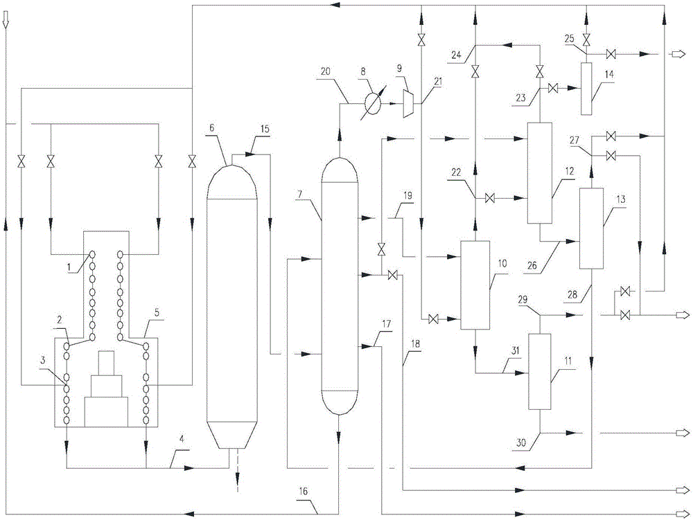
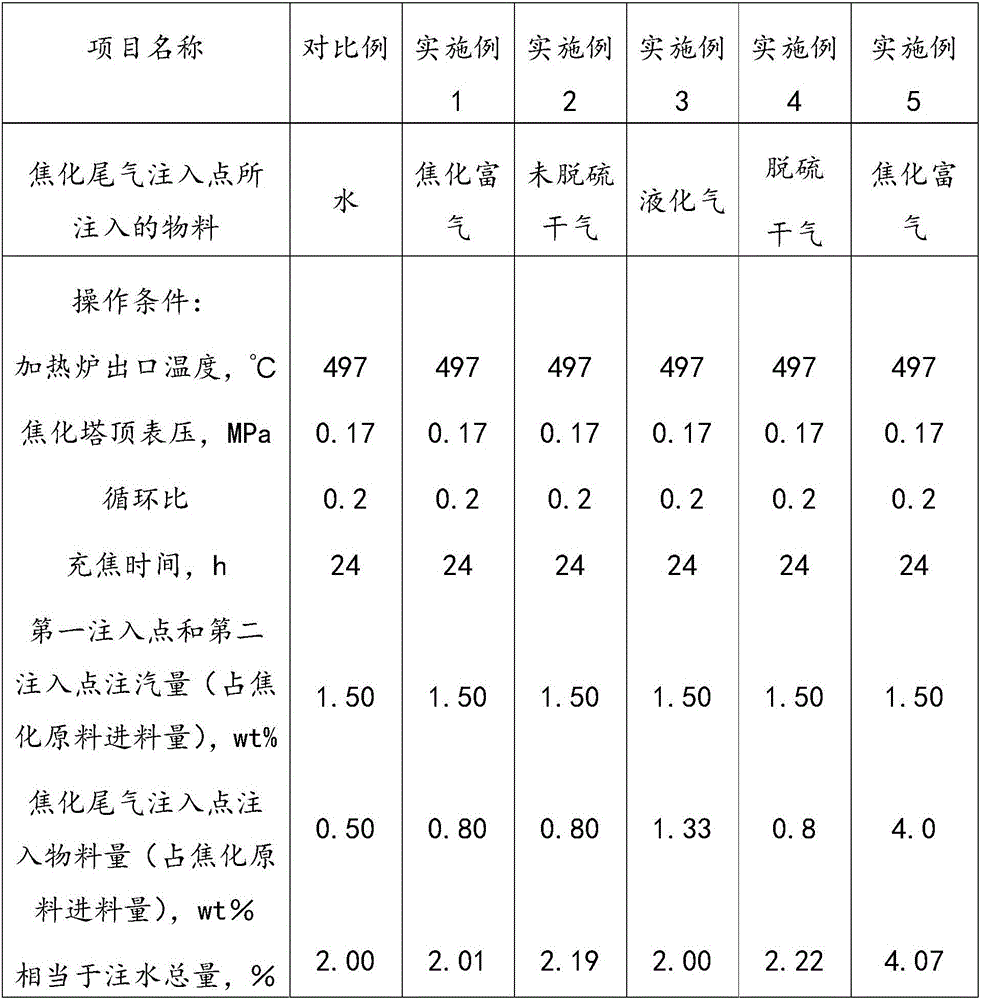
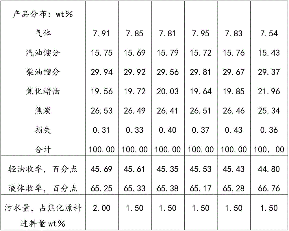
[0053] use figure 1 The heavy oil delayed coking unit shown uses vacuum residue as coking raw material (see Table 1 for the properties of vacuum residue), the temperature at the outlet of heating furnace 5 is 497°C, the pressure at the top of coking tower 6 is 0.17Mpa, the first injection point and the second The total amount of water injection at the second injection point accounts for 1.5wt% (0.75wt%) of the coking raw material feed amount and under the condition of a circulation ratio of 0.2, the high-temperature material from the outlet of the radiant section of the heating furnace 5 enters the coking tower 6 for coking reaction The high-temperature oil and gas generated enters the fractionation tower 7 for separation after quenching; the coking rich gas (C1-C4 components) obtained from the top of the fractionation tower 7 through cooling and separation is pressurized to about 1.2MPa by the rich ga...

Embodiment 2

[0057] Use the method and device described in Example 1 to carry out delayed coking of heavy oil, the difference is that only the dry gas before desulfurization from the gasoline absorption and recirculation dry gas pipeline 24 replaces the coking rich gas and enters the radiant section of the heating furnace 5, which is the fourth from bottom to top Furnace tube 3.

Embodiment 3

[0059] Using the method and device described in Example 1 to carry out delayed coking of heavy oil, the difference is that only the liquefied gas from the liquefied gas pipeline replaces the coking rich gas and enters the fourth furnace tube 3 from bottom to top in the radiant section of the heating furnace 5, and its injection volume accounts for 1.33wt% of the coking raw material feed amount.


PUM


Abstract

The invention provides a delayed coking method and apparatus for heavy oil; according to the method, coking tail gas is injected into a heating furnace radiating segment tube under delayed coking operational process conditions, operating is simple, the required apparatus is simple in structure, the coking tail gas, instead of steam, is injected into the heating furnace radiating segment tube, usage of steam is effectively reduced, the defect that existing coking heating furnace is injected with much water is overcome, processing energy consumption of the apparatus is reduced, sewage emission is decreased, liquid yield of the coking apparatus can be increased through circulation of partial coking tail gas, and especially the yield of coker gas oil is evidently increased.

Description

technical field [0001] The invention relates to the field of petrochemical technology, in particular to a method and device for delayed coking of heavy oil. Background technique [0002] Delayed coking, as one of the heavy oil processing methods, has been used in the oil refining industry for many years. This process uses heavy and low-quality residual oil as raw material. After being heated by a heating furnace, it enters the coking tower, where thermal decomposition and condensation reactions occur in the coking tower. Boiling point liquids, gases and coke products. [0003] At present, the raw materials of the delayed coking unit in the refinery are getting heavier and heavier. Some low-quality raw materials have a coke yield as high as 30-40wt% under the condition of circulation operation, and the heating furnace tube is severely coked and the liquid yield is low. Due to the influence of factors such as furnace tube coking and high coke yield, the development of delayed...

Claims


Application Information

Patent Timeline
Patent Type & Authority Applications(China)
IPC IPC(8): C10G9/20C10G9/36C10G55/04
CPCC10G9/20C10G9/36C10G55/04
Inventor 韩海波王洪彬宋业恒李康黄新龙刘淑芳王少峰胡艳芳赵智刚张晓燕李晓昌房传兴
Owner SINOPEC ENG GRP CO LTD
Why Eureka
Try Eureka