
Electrochemical polishing method for magnesium metal component

A metal component, electrochemical technology, applied in the field of electrochemical polishing, can solve the problems of difficult precision and small magnesium metal components, complex shapes, time-consuming and manpower

Active Publication Date: 2017-02-22
张无量
View PDF5 Cites 3 Cited by
  • Summary
  • Abstract
  • Description
  • Claims
  • Application Information

AI Technical Summary

Problems solved by technology

[0003] However, general mechanical polishing is done manually. In addition to being time-consuming and labor-intensive, it is often impossible to make the magnesium metal parts have a uniform finishing surface due to manual errors.
Moreover, the mechanical polishing method is difficult to apply to precise and small magnesium metal components. For example, the magnesium alloy stent used in medical treatment is not only small in size but also has a rather complicated shape, so it cannot be mechanically polished. The way to achieve the purpose of surface finishing

Method used


Image

  • Electrochemical polishing method for magnesium metal component
  • Electrochemical polishing method for magnesium metal component
  • Electrochemical polishing method for magnesium metal component

Examples


Embodiment 1

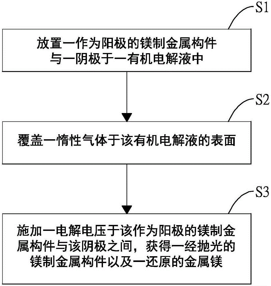
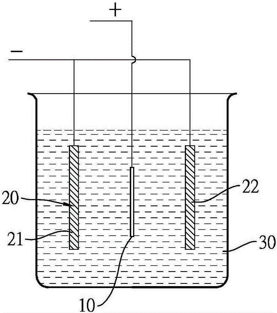
[0028] see figure 1 and figure 2 , The electrochemical polishing method of the magnesium metal member of this embodiment is as follows. In this embodiment, the metal member 10 made of magnesium is a metallographic test piece containing 98wt% magnesium.

[0029] First, as described in step S1 , the magnesium metal member 10 is used as an anode, and the magnesium metal member 10 and a cathode 20 are placed in an organic electrolyte 30 . In this embodiment, the cathode 20 is stainless steel; the organic magnesium electrolyte 30 includes a solvent, an organic electrolyte and a supporting electrolyte, the solvent is 1L of tetrahydrofuran, the organic electrolyte is ethylmagnesium chloride, and the supporting electrolyte is chlorine Aluminum chloride; wherein, in the organic magnesium electrolyte solution 30 of 1L, the mole number of the organic magnesium electrolyte in the organic electrolyte solution 30 is 1.5mole and the mole number concentration of the supporting electrolyte ...

Embodiment 2

[0035] The electrochemical polishing method of the magnesium metal member in this embodiment is generally the same as the electrochemical polishing method of the magnesium metal member in the first embodiment. Differences between this embodiment and Embodiment 1 are as follows.

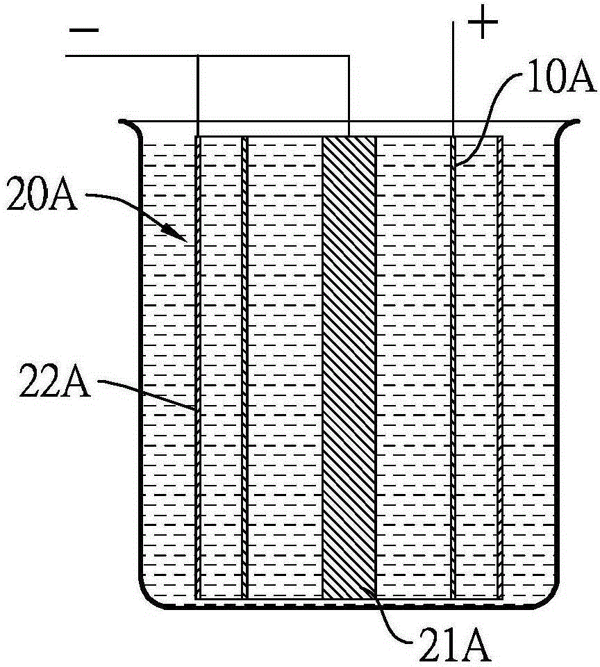
[0036] see image 3 , Figure 4 As shown, in this embodiment, the magnesium metal member 10A is a vascular stent, the vascular stent is a cylinder with a mesh wall, and the vascular stent is used as an anode, and the first cathode of the cathode 20A The component 21A penetrates the inner side of the magnesium metal component 10A, and the second cathode component 22A of the cathode 20A is sheathed on the outside of the vascular stent. Wherein, the magnesium metal component 10A is made of a magnesium-tin alloy. Based on the whole magnesium-tin alloy, the magnesium content of the magnesium-tin alloy is 95wt%, and the tin content of the magnesium-tin alloy is 5wt%.

[0037] In this embodiment, the magn...


PUM


Abstract

The invention discloses an electrochemical polishing method for a magnesium metal component. The electrochemical polishing method comprises the following steps of firstly, putting an anode and a cathode into an organic magnesium electrolyte solution, wherein the anode is the magnesium metal component; and then, applying an electrolysis voltage between the anode and the cathode to obtain a polished magnesium metal component. The organic electrolyte solution comprises a solvent selected from a group consisting of ethyl ether, tetrahydrofuran, 2-methyl tetrahydrofuran and cyclopentyl methyl ether, and an organic magnesium electrolyte selected from a group consisting of methyl magnesium chloride, ethyl magnesium chloride, phenyl magnesium chloride, alkoxy magnesium bromide and alkoxy magnesium chloride. The electrochemical polishing method for the magnesium metal component disclosed by the invention has the advantages of saving time, saving labor, and being suitable for fine magnesium metal components.

Description

technical field [0001] The invention relates to an electrochemical polishing method, in particular to an electrochemical polishing method for magnesium metal components. Background technique [0002] Magnesium metal components have been widely used in transportation, electronic products and implants in recent years due to their light weight, high specific strength, good heat dissipation, good electromagnetic shielding, good impact resistance and good recyclability. In the field of sexual medical equipment. In order to ensure that magnesium metal components can have good quality and finishing surface, it is necessary to carry out metallographic analysis and surface finishing treatment on magnesium metal components, and when performing metallographic analysis and surface finishing treatment, it is necessary to separately Metallographic test pieces and rough-processed products of magnesium metal components are mechanically polished to obtain clear metallographic photos and fin...

Claims


Application Information

Patent Timeline
IPC IPC(8): C25F3/18C25F7/00
CPCB23H3/00C25F3/18
Inventor 赵俊刚张无量赵海心
Owner 张无量
Learn More