Biomass heat energy power system based on working medium circulation condensation

A technology of working fluid circulation and power system, which is applied in steam/steam condensers, indirect heat exchangers, heat exchanger types, etc., and can solve the problems of easy deterioration of working fluid or impurities, large waste of heat energy in condensing devices, and problems of working fluid gas To solve problems such as unstable temperature, to achieve the effect of increasing heat conversion efficiency, increasing the amount of work done, and improving work conversion efficiency

Inactive Publication Date: 2017-02-22
郭远军
View PDF0 Cites 0 Cited by
  • Summary
  • Abstract
  • Description
  • Claims
  • Application Information

AI Technical Summary

Problems solved by technology

[0009] The purpose to be achieved by the present invention is: aiming at the existing heat energy equipment, reducing the heat displacement and heat energy waste, accelerating the condensation rate, improving the heat energy conversion efficiency, stabilizing the gasification temperature and the flow rate of the working medium, improving the quality of the working medium, preventing The deterioration of the working medium accelerates the heat absorption of gasification; at the same time, comprehensive utilization of straw and firewood is used to solve the existing thermal energy equipment in the above background technology: low heat conversion efficiency, unstable gasification temperature of the working medium, and poor condensation effect of the working medium Good, the working medium is easy to deteriorate or appear impurities, gasification heat absorption is slow, the heat source requires a high temperature, the heat energy waste of the condensing device is large, the condensation rate is slow, or additional power consumption is required; and solve the pollution that exists when the straw is directly incinerated Problems and Energy Waste Problems

Method used


Image

  • Biomass heat energy power system based on working medium circulation condensation
  • Biomass heat energy power system based on working medium circulation condensation
  • Biomass heat energy power system based on working medium circulation condensation

Examples


Embodiment 1

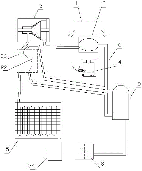
[0082] Embodiment one (such as figure 1 shown): a biomass thermal energy power system based on the circulating condensation of working fluid, including a heat collecting device 1, a gasification device 2, a turbine 3, a biomass furnace 4, a condensing device 5, a circulating pipeline 6, a circulating working medium 7 and The one-way hydraulic pump 9, the gasification device 2, the turbine 3, the condensing device 5 and the one-way hydraulic pump 9 realize circulation communication through the circulation pipeline 6 in sequence. The circulation pipeline 6 contains a circulating working medium 7, and the heat collection device 1 is installed Outside the device 2, it is used for gasification and heating of the working fluid in the gasification device 2;

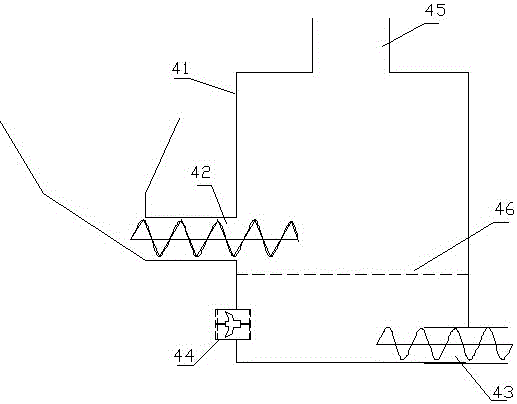
[0083] (Such as figure 2 As shown) the biomass furnace 4 includes a combustion furnace 41, a screw feeder 42, a spiral ash discharger 43, a blower 44 and a heat exhaust port 45. The middle and lower part of the combustion furn...

Embodiment 2

[0096] Embodiment two (such as Figure 6 Shown): The difference from Embodiment 1 is that the heat collecting device 1 includes an upper cover 11 and a lower cover 12, a heating port 13 is provided in the middle of the lower cover 12, and the upper cover 11 and the lower cover 12 are respectively located on the upper and lower sides. Between 11 and the lower cover 12 is a heat collecting chamber 14, two layers of upper cover protruding rings 111 are distributed on the lower part of the upper cover 11 of the heat collecting device 1, and two layers of lower cover protruding rings 121 are distributed on the upper part of the lower cover 12 of the heat collecting device 1, The protruding ring 111 of the upper cover and the protruding ring 121 of the lower cover are staggered.

[0097] By conducting experiments on the biomass thermal energy power system based on working fluid circulation condensation in the above-mentioned embodiment 2, by adjusting the biomass delivery rate and ...

Embodiment 3

[0098] Embodiment three (such as Figure 7 Shown): The difference from Embodiment 1 is that the lower part of the upper cover 11 of the heat collecting device 1 is provided with a three-layer upper cover protruding ring 111, and the upper part of the lower cover 12 of the heat collecting device 1 is distributed with a three-layer lower cover protruding ring 121 , the upper cover protruding ring 111 and the lower cover protruding ring 121 are staggered.

[0099] By conducting experiments on the biomass thermal energy power system based on working fluid circulation condensation in the above-mentioned embodiment 3, by adjusting the biomass delivery rate and blast rate, the temperature of the combustion furnace 41 is controlled at 120°C, 150°C, and 200°C, respectively. , 250°C, 300°C, 400°C, the flow rate of the working medium in the circulation pipe is adjusted according to the operating stability of the biomass thermal energy power system based on the circulating condensation o...


PUM


Abstract

The invention discloses a biomass heat energy power system based on working medium circulation condensation. The biomass heat energy power system comprises a gasification device, a turbine, a condensing unit and a one-way hydraulic pump which circularly communicate with one another sequentially through circulating pipelines. The circulating pipelines internally contain a circulating working medium. A heat collection device is installed outside the gasification device and communicates with a biomass furnace. The gasification device comprises a gasification cavity and a preheating cavity pipe. A pre-condensation cavity is arranged at the exhaust port position of the turbine, and the preheating cavity pipe makes parallel contact with the pre-condensation cavity. The biomass heat energy power system based on working medium circulation condensation can accelerate condensation, improve the efficiency of the turbine and reduce the heat energy exhaust amount, and therefore the heat energy conversion efficiency is improved.

Description

technical field [0001] The invention belongs to the field of energy utilization equipment, in particular to a biomass thermal energy power system based on working medium circulation condensation. Background technique [0002] Energy is an important material basis for the survival and development of human society. Throughout the history of the development of human society, every major progress of human civilization is accompanied by the improvement and replacement of energy. The development and utilization of energy has greatly promoted the development of the world economy and human society. [0003] However, with the continuous development and consumption of energy, non-renewable energy sources such as petroleum, coal mines, and natural gas are gradually reduced, and energy conservation and recycling are gradually being valued. The basic content of my country's current energy strategy is: adhere to the priority of conservation, based on domestic, diversified development, r...

Claims


Application Information

Patent Timeline
Patent Type & Authority Applications(China)
IPC IPC(8): F01K11/02F01K25/08F01K25/10H02N11/00F28B5/00F28D1/02B01D1/00B01D1/16
CPCF01K11/02B01D1/00B01D1/16F01K25/08F01K25/10F01K25/106F28B5/00F28D1/0206H02N11/002
Inventor 郭远军
Owner 郭远军
Why Eureka
Try Eureka