
Combustion detection system and combustion detection method thereof

A detection system and optical detection technology, applied in measurement devices, heat measurement, instruments, etc., can solve a lot of problems such as time adjustment, laser deviation, etc.

Active Publication Date: 2017-02-22
NANJING SCIYON AUTOMATION GRP +1
View PDF7 Cites 5 Cited by
  • Summary
  • Abstract
  • Description
  • Claims
  • Application Information

AI Technical Summary

Problems solved by technology

This method requires a lot of time to install and adjust to ensure that the optical axis of the incident end is coaxial with the optical axis of the receiving end
At the same time, due to the large temperature change in the furnace from preheating to full load, the deformation of the furnace wall will cause the deviation of the collimation at the two ends of the transceiver and cause the laser to deviate. The deformation of the TDLAS has a great impact on the repeated use of the TDLAS detection and combustion system. Therefore, before the boiler is started (that is, in the case of a cold machine), it is necessary to perform frequent alignment and adjustment operations on the receiving and receiving optical circuits.

Method used


Image

  • Combustion detection system and combustion detection method thereof
  • Combustion detection system and combustion detection method thereof
  • Combustion detection system and combustion detection method thereof

Examples


Embodiment Construction

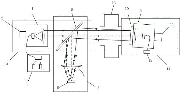
[0025] The combustion detection system of the present invention will be described in detail below in conjunction with the accompanying drawings.

[0026] Such as figure 1 As shown, the combustion detection system of the present invention can quickly align and measure the deformation of the furnace wall under cold machine conditions. Ⅰ3. Laser switching device 4, optical path calibration device, receiving device 9, optical filter 10, turntable II11, photoelectric detector 12, mechanical cantilever II14. The boiler temperature field 13 is located in the boiler furnace. Turntable I and turntable II are orthogonal rotary turntables that rotate orthogonally in the horizontal and vertical directions, and can be manually adjusted or controlled by the turntable.

[0027] The emission end of the combustion detection system is composed of the emission device 1, the turntable I2, the mechanical cantilever I3, the laser switching device 4, and the optical path calibration device. The o...


PUM


Abstract

The invention discloses a combustion detection system and a combustion detection method thereof. The combustion detection system disclosed by the invention comprises a transmitting terminal fixing device, a rotating table I, a transmitting device, a laser switching device, an optical path calibration device, a receiving terminal fixing device, a rotating table II, an optical filter, a receiving device and a photoelectric detector; the rotating table I and the rotating table II are respectively fixed on the transmitting terminal fixing device and the receiving terminal fixing device; the transmitting device is fixedly arranged on the rotating table I; the optical path calibration device is detachably arranged on the transmitting terminal fixing device; the laser switching device is connected with the transmitting device by optical fibers; the optical filter and the receiving device are coaxially fixed on the rotating table II; the receiving device is connected with the photoelectric detector by optical fibers; when an optical path is calibrated, the transmitting device transmits indicating light, the indicating light passes through the optical path calibration device and a furnace sequentially, then is reflected by the optical filter and enters into the optical path calibration device for calibration of the optical path. The combustion detection system disclosed by the invention can carry out rapid alignment when a boiler is in a cold state.

Description

technical field [0001] The invention relates to a combustion detection system and a combustion detection method thereof, in particular to a combustion detection system and a combustion detection method capable of measuring furnace wall deformation and quickly collimating and repairing under a cold machine. Background technique [0002] In China, the vast majority of electricity comes from thermal power generation. But now thermal power generation is very polluting and inefficient. while temperature and CO 2 Concentration, etc. are important parameters of combustion in the furnace. Optical sensors based on the principle of laser spectroscopy have been used to solve the problem of concentration component measurement related to extraction measurement technology, and measurement technology based on laser principle also has the advantage of providing high-speed feedback suitable for dynamic process control. [0003] Existing technologies mostly use tunable diode laser absorpti...

Claims


Application Information

Patent Timeline
IPC IPC(8): G01B11/16G01K13/00G01N21/84G01N21/01
CPCG01B11/16G01K13/00G01N21/01G01N21/84G01N2021/0112
Inventor 胡歙眉刘国耀周阳陈昊谢斌
Owner NANJING SCIYON AUTOMATION GRP
Learn More