Automatic clock frequency measurement and calibration system and method

A clock frequency and calibration system technology, which is applied in the direction of measuring electricity, measuring devices, and measuring electrical variables, etc., can solve the problems of difficult clock frequency measurement and calibration, low MCU operating frequency, and low efficiency of a single calibration mode

Active Publication Date: 2017-02-22
CHIPSEA TECH SHENZHEN CO LTD
View PDF6 Cites 10 Cited by
  • Summary
  • Abstract
  • Description
  • Claims
  • Application Information

AI Technical Summary

Problems solved by technology

[0003] At present, the clock frequency measurement device measures the 1MHz clock signal. The higher the measurement frequency, the greater the clock deviation. The actual measurement frequency has an error of 1% between the high frequency 500K-1000K. The improvement of the measurement error becomes larger, and the higher the measurement accuracy, the system design cost, complexity and subsequent maintainability have brought troubles. It is necessary to design a clock measurement and calibration that can make the system have higher accuracy with the help of external instrumentation equipment. ;The current chip clock frequency measurement and calibration platform is developed based on 8-bit MCU. Its program code cannot be updated online, its own processing ability is not strong and there is no information prompt, etc., which bring difficulties to clock frequency measurement and calibration, and the MCU has a low operating frequency. The slow execution speed of instructions and instructions is not conducive to the maintenance and program upgrade of subsequent developers; the clock frequency measurement and calibration system based on ATE test machine has high cost in the FT test stage, and its machine language versatility and program portability are poor, etc. , due to the poor versatility and portability, it brings great inconvenience to the follow-up personnel maintenance, and because the test machine is relatively expensive, it is inconvenient to move and carry, which brings some practical problems to the user; the previous platform test and programming system were separated , online programming is not possible, the integration of the platform is low, and the chip needs to be taken out every time the program is updated, resulting in increased workload and low work efficiency; single calibration mode is low in efficiency, and at the same time, only one chip can be tested in mass production mode Calibration; test calibration requires two independent systems to complete, and the firmware cannot be upgraded online, which will affect the cost and system reliability, resulting in high development and maintenance costs
[0004] At the same time, the test and calibration system using the 8-bit MCU architecture is greatly restricted in the measurement of the data clock rate, and cannot meet the clock frequency measurement and calibration requirements of the current high clock frequency chips, and requires a great deal of support in the communication interface. It is limited to the communication rate of the supporting software of the purchased chip and the communication rate of the chip itself; the traditional clock frequency measurement and calibration is only used in the burning mode, and the use mode or scene is single, and it is impossible to grasp the chip in the user mode in time. Performance, which seriously affects the display of chip performance

Method used


Image

  • Automatic clock frequency measurement and calibration system and method
  • Automatic clock frequency measurement and calibration system and method
  • Automatic clock frequency measurement and calibration system and method

Examples


Embodiment Construction

[0057] In order to make the object, technical solution and advantages of the present invention clearer, the present invention will be further described in detail below in conjunction with the accompanying drawings and embodiments. It should be understood that the specific embodiments described here are only used to explain the present invention, not to limit the present invention.

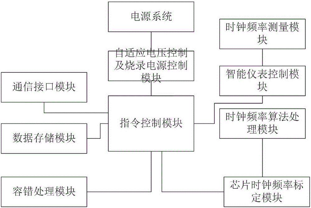
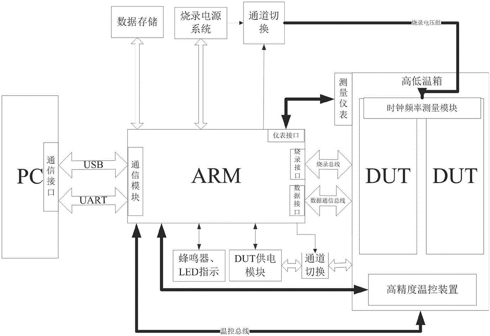
[0058] figure 1 Shown is the hardware block diagram realized by the present invention, figure 2 It is a diagram of an application example of the present invention. As shown in the figure, the automatic clock frequency measurement and calibration system can not only perform clock frequency measurement and calibration for chips purchased by developers and customers in an integrated manner, but also can be used as a set of clock frequency The frequency test system is used to demonstrate the clock frequency performance of the product. At the same time, the clock frequency measurement and calibration...


PUM


Abstract

The invention discloses an automatic clock frequency measurement and calibration system and method. The system comprises a power supply system, an instruction control module, a data storage model, a self-adaptive voltage control and burning power supply control module, a communication interface module, a clock frequency measurement module, a chip clock frequency calibration module, a clock frequency algorithm processing module, a smart instrument control module and a clock calibration module. The invention achieves measurement and calibration of clock frequencies of integrated or professional chips at low cost, the frequency calibration accuracy is ensured, demands of high-precision clock frequency calibration are stratified, usage requirements of clients are met with low investment and high benefits, the chip design cost is saved and the development efficiency is improved.

Description

technical field [0001] The invention belongs to the technical field of integrated circuits, and in particular relates to a correction and frequency measurement device and method for an integrated in-chip clock frequency module or a dedicated clock chip. Background technique [0002] After the chip is manufactured, it is often necessary to correct its clock frequency index due to various reasons such as the inherent deviation of the internal clock frequency division circuit of the chip, the defects of the wafer production process, and the temperature drift caused by various application environments, so as to meet the requirements of the actual application system. The use accuracy of the clock chip in the system, and can perform clock measurement and calibration for chips with various storage structures. [0003] At present, the clock frequency measurement device measures the 1MHz clock signal. The higher the measurement frequency, the greater the clock deviation. The actual m...

Claims


Application Information

Patent Timeline
Patent Type & Authority Applications(China)
IPC IPC(8): G01R31/317
CPCG01R31/31727
Inventor 庞新洁
Owner CHIPSEA TECH SHENZHEN CO LTD
Why Eureka
Try Eureka