Magnetic suspension optical scanning range finding device and method

An optical scanning and distance measuring device technology, applied in the field of distance measurement, can solve the problems of affecting service life and easy wear of devices, and achieve the effect of no mechanical wear parts and compact size

Pending Publication Date: 2017-02-22
北京创想智控科技有限公司
View PDF4 Cites 6 Cited by
  • Summary
  • Abstract
  • Description
  • Claims
  • Application Information

AI Technical Summary

Problems solved by technology

[0007] The purpose of the present invention is to provide a magnetic levitation optical scanning distance measuring device and method to ...

Method used


Image

  • Magnetic suspension optical scanning range finding device and method
  • Magnetic suspension optical scanning range finding device and method
  • Magnetic suspension optical scanning range finding device and method

Examples


Embodiment 1

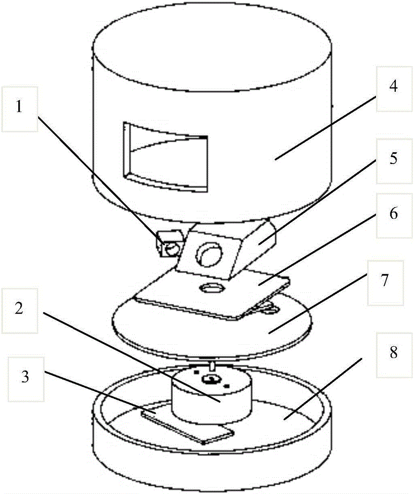
[0050] Such as Figure 1-3 As shown, a magnetic levitation optical scanning distance measuring device is provided in this embodiment, and the magnetic levitation optical scanning distance measuring device includes a fixed base 8, an angle encoder, a rotation system, a laser distance measuring system, a power supply transmission and a data receiving device 3. Power supply receiving and wireless data transmission device 9 and data processing module;

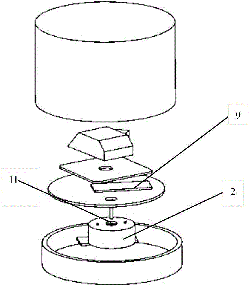
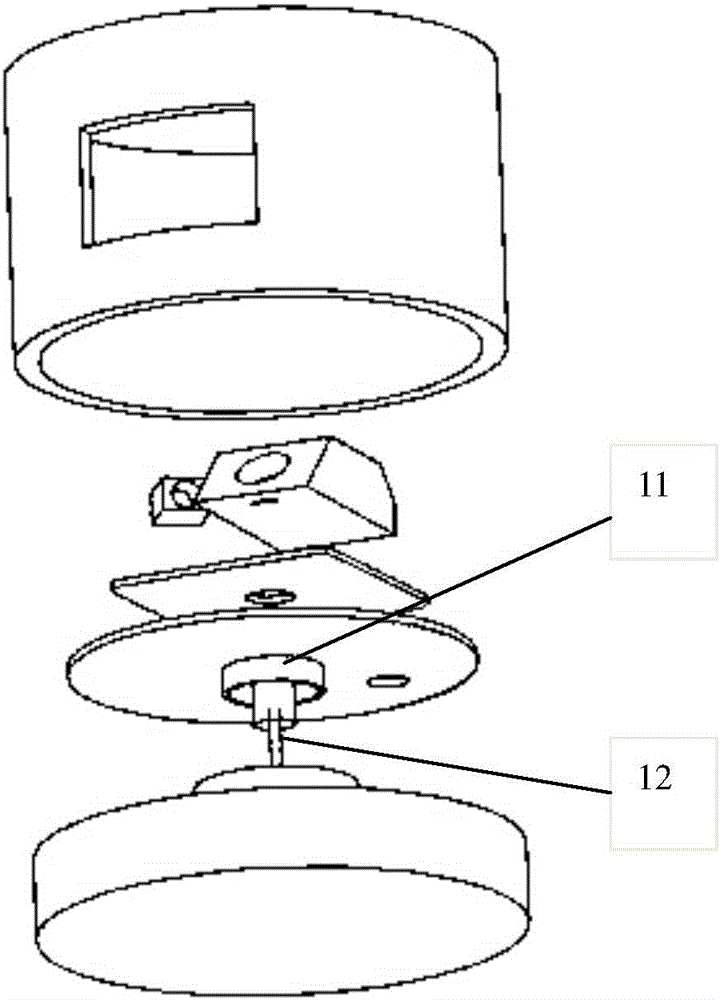
[0051] The rotating system includes a rotating platform 6, a motor, a magnetically permeable ring 11 and an annular permanent magnet 2; the permanent magnet 2 is rotationally connected with the fixed base 8; the center of the permanent magnet 2 is provided with a needle shaft socket 10 One end of the needle shaft 12 is inserted in the needle shaft socket 10, and the other end of the needle shaft 12 is affixed to the inner wall of the magnetic conduction ring 11; the upper end of the magnetic conduction ring 11 is connected to the r...

Embodiment 2

[0077] The optical scanning distance measuring method provided in this embodiment is implemented on the maglev optical scanning distance measuring device provided in the first embodiment.

[0078] Specifically, the optical scanning ranging method includes:

[0079] Step 1, start the motor, the motor drives the permanent magnet 2 to rotate, and the permanent magnet 2 drives the rotating platform 6 to rotate through the magnetic ring 11; the angle encoder monitors the rotating platform 6 rotating speeds, after the rotating speed of described rotating platform 6 stabilizes, enter next step;

[0080] Step 2. The laser light source 1 irradiates the laser beam onto the target object;

[0081] Step 3, the target object reflects the laser beam generated by the laser light source 1;

[0082] Step 4. The photosensitive device 5 receives the emitted light and converts the image signal into an electrical signal; wherein, the reflected light passes through the imaging lens and converges ...


PUM


Abstract

The invention provides a magnetic suspension optical scanning range finding device and method, relating to the field of range finding. The magnetic suspension optical scanning range finding device includes a fixed base, an angle encoder, a rotating system, a laser range finding system, a power supply transmission and data reception device, a power supply reception and wireless data transmission device, and a data processing module, the rotation of the laser range finding system is realized by a magnetic suspension device to prevent machinery wearing, the power supply reception and wireless data transmission device is used to receive data and electrical energy transmitted by the power supply transmission and data reception device, and the power supply reception and wireless data transmission device supplies power to the laser range finding system, so that the wire wearing can be prevented. The invention solves the technical problems that a small-sized laser radar internal device in the prior art is easy to wear and influences the service life.

Description

technical field [0001] The invention relates to the technical field of distance measurement, in particular to a magnetic levitation optical scanning distance measurement device and method. Background technique [0002] The optical scanning ranging device is a device for non-contact scanning ranging of the target object through structured light. Scanning the structured light beam to the environment through the rotating mechanism can realize the extraction of environmental contour information. [0003] Compared with methods such as ultrasonic waves and depth cameras, laser has the characteristics of high coherence and high directionality, which can greatly improve the measurement accuracy, so it is widely used in distance measuring devices. The laser ranging method has the characteristics of fast measurement speed and long range. At present, many indoor robot systems use laser ranging devices as sensors to realize positioning, construct maps and barriers. [0004] Laser rang...

Claims


Application Information

Patent Timeline
IPC IPC(8): G01S17/08
CPCG01S17/08
Inventor 凌清吴兴华宋仕超陈猛
Owner 北京创想智控科技有限公司
Why Eureka
Try Eureka