
Wireless energy transmission intelligent charging device

A technology of wireless power transmission and intelligent charging, which is applied in battery circuit devices, circuit devices, electric vehicle charging technology, etc., can solve problems such as increasing the volume and weight of loosely coupled transformers, increasing equipment costs, and being unfavorable for lightweight vehicles. Achieve the effects of improving capacity and transmission efficiency, improving coupling coefficient, and increasing curb quality

Pending Publication Date: 2017-02-22
BEIJING INSTITUTE OF TECHNOLOGYGY
View PDF6 Cites 16 Cited by
  • Summary
  • Abstract
  • Description
  • Claims
  • Application Information

AI Technical Summary

Problems solved by technology

However, achieving high transmission efficiency and high transmission capacity through this method will increase the volume and weight of the entire loosely coupled transformer
This solution not only increases the cost of equipment, is not conducive to the promotion and application of wireless charging, but also increases the curb weight of electric vehicles, which is not conducive to the lightweight of the whole vehicle

Method used


Image

  • Wireless energy transmission intelligent charging device
  • Wireless energy transmission intelligent charging device
  • Wireless energy transmission intelligent charging device

Examples


Embodiment 1

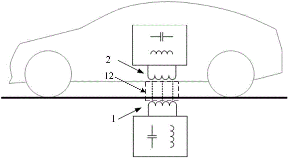
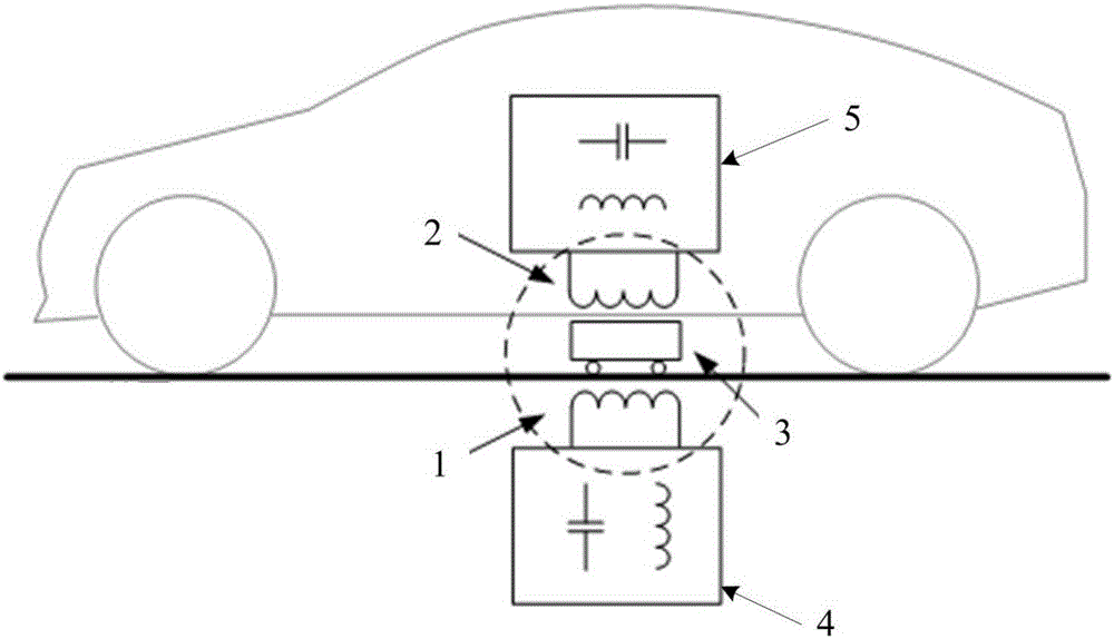
[0042] Example 1: The schematic diagram of a traditional wireless charging device for electric vehicles is as follows figure 1 As shown, its specific structural diagram is shown in figure 2 shown. The primary side transmitting coil 1 is arranged underground corresponding to the parking space when the electric vehicle is charged, the position of the primary side transmitting coil 1 is a preset charging position, and the secondary side coil 2 is installed on the electric vehicle. When the electric vehicle is parked at the preset charging position on the parking space, the primary side transmitting coil 1 and the secondary side receiving coil 2 form a loosely coupled transformer, and the magnetic coupling area of ​​the loosely coupled transformer is 12 . The high-frequency magnetic field emitted by the primary transmitting coil 1 can be received by the secondary receiving coil 2 through electromagnetic induction or electromagnetic vibration, and then converted into electrical e...


PUM


Abstract

The invention disclose a wireless energy transmission intelligent charging device, including a loose coupling voltage transformer and a mobile relay coupler, the original edge emission coil of the loose coupling voltage transformer is provided under the ground, and is used for launching magnetic field energy, a secondary receiving coil is provided on an electricity receiving device, and is connected with the electricity receiving device, and when the secondary receiving coil reaches the location of the original edge emission coil, the electricity receiving device sends out an electricity charging order; the mobile relay coupler according to the electricity charging order moves to the location of the original edge emission coil, and transmits the magnetic field energy of the original edge emission coil to the secondary receiving coil, the secondary receiving coil converts the received magnetic field energy to electric energy and outputs to the electricity receiving device. The mobile relay coupler is located between a base plate of the electric car and the ground, increases the coupling coefficients of the coil in the loose coupling voltage transformer, thereby increasing the ability of electricity energy transmission and the efficiency of transmission. Because of the separate installation of the mobile relay coupler and the electric car, the device cannot add to the kerb mass of electric cars.

Description

technical field [0001] The invention relates to the field of wireless charging, in particular to a mobile intelligent charging device for wireless energy transmission. Background technique [0002] Non-contact power supply uses magnetic field coupling to realize "wireless power supply", that is, a non-contact transformer with completely separated primary and secondary sides is used to transmit electric energy through high-frequency magnetic field coupling, so that the primary side (power supply side) and secondary side ( consumption side) without physical connection. Compared with the traditional contact power supply, the non-contact power supply is convenient and safe to use, not prone to leakage, no spark and electric shock hazard, no dust accumulation and contact loss, no mechanical wear and corresponding maintenance problems, and can adapt to a variety of severe weather and environments , it is convenient to realize automatic power supply, has good application prospect,...

Claims


Application Information

Patent Timeline
Patent Type & Authority Applications(China)
IPC IPC(8): H02J50/12H02J7/02B60L11/18
CPCH02J5/005H02J7/025B60L53/12Y02T10/70Y02T10/7072Y02T90/14
Inventor 邓钧君王震坡庞博刘鹏
Owner BEIJING INSTITUTE OF TECHNOLOGYGY
Learn More