Integrated high-speed rotating cooling machine

A technology of high-speed rotation and cooling machine, which is applied in the direction of cooling/ventilation/heating transformation, DC voltage accelerator, electrical components, etc. It can solve the problems of complex force, unsuitable, large size and volume of the gearbox, and achieve stable work Guaranteed performance and reliability, compact overall structure, and high-speed rotation

Active Publication Date: 2017-02-22
合肥华升泵阀股份有限公司
View PDF6 Cites 0 Cited by
  • Summary
  • Abstract
  • Description
  • Claims
  • Application Information

AI Technical Summary

Problems solved by technology

However, the currently used large-diameter coolers are limited by the size and volume of the speed-up box, the force is more complicated, and the stability is poor, so it is very unsuitable for fine neutron generation operations.
However, the shaft diameter of the traditional high-speed cooling machine is relatively small. Once it is applied to the above-mentioned fields, it will lead to narrowing of the deuterium ion beam channel, thereby making the utilization rate of the target plate relatively low.

Method used


Image

  • Integrated high-speed rotating cooling machine
  • Integrated high-speed rotating cooling machine
  • Integrated high-speed rotating cooling machine

Examples


Embodiment Construction

[0033] For ease of understanding, here in conjunction with accompanying drawing, to the concrete implementation structure of the present invention, be further described as follows:

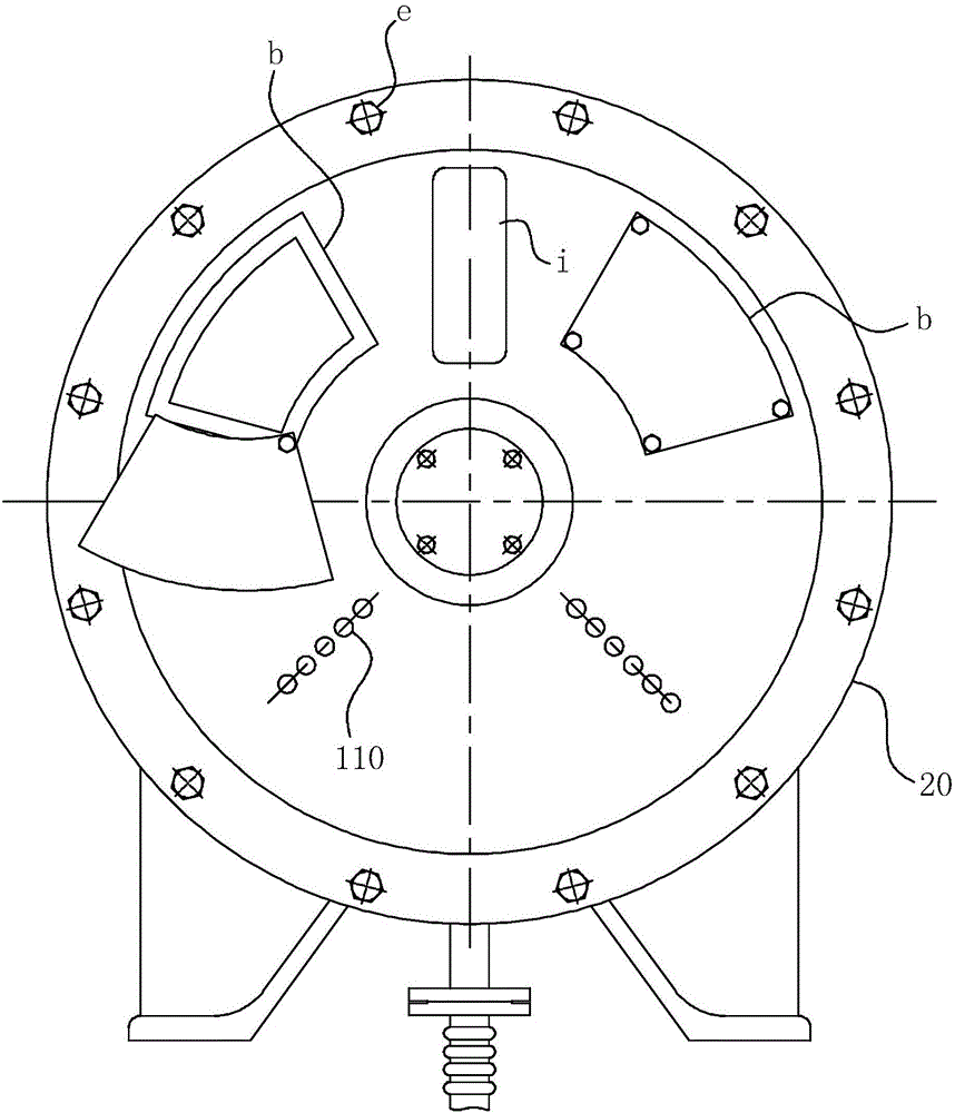
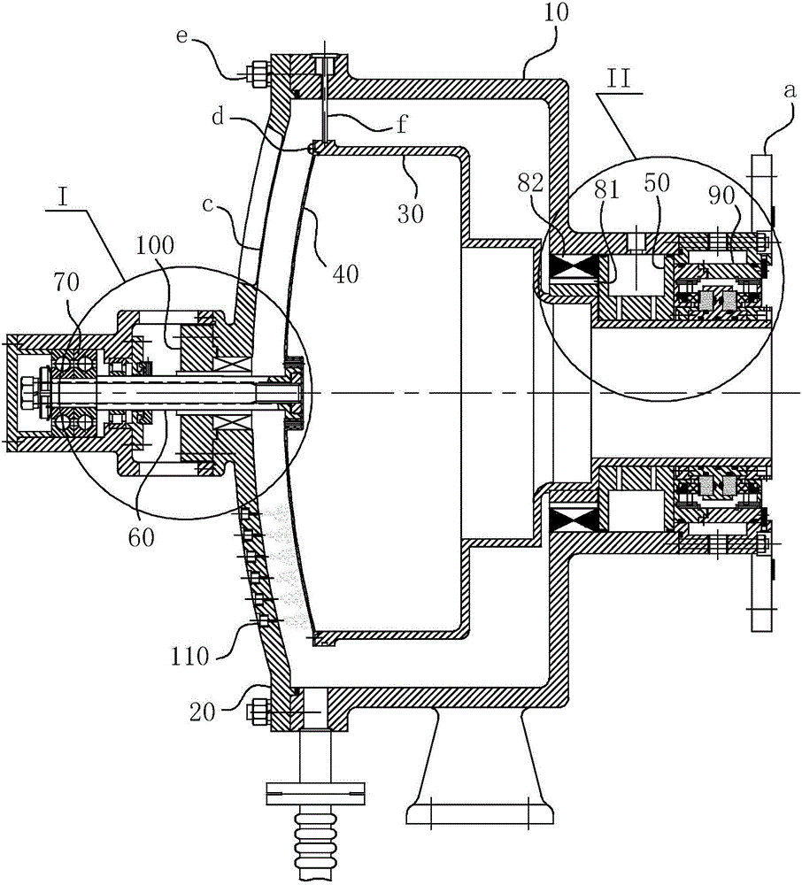
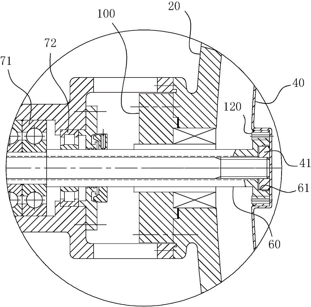
[0034] Concrete structure of the present invention, as Figure 1-4 As shown, its overall structure is a support structure at both ends, mainly composed of air bearing 50, rolling bearing 70, dry gas seal 90, contact mechanical seal 100, stator 82, rotor 81, rotating cavity 30, cooler casing (that is, casing Body 10), shell cover 20, atomizing nozzle 110, target piece 40 and connecting flange a and so on. Among them, such as figure 1 As shown, the power unit of the device is mainly composed of a stator 82 and a rotor 81. The rotor 81 is directly hooped on the rotating cavity 30, which ensures the reliability and compactness of the driving part. The radial support force and axial force of the device are determined by the figure 2 The air bearing 50 at the right side of the structure and the f...


PUM


Abstract

The invention belongs to the field of high-speed rotating cooling machines, and particularly relates to an integrated high-speed rotating cooling machine. The integrated high-speed rotating cooling machine comprises a housing body, a housing cover and a rotating shaft, wherein the housing cover and the cylinder wall of a large-caliber section of the housing body are enclosed to form an accommodating space for accommodating a rotating target film assembly; the rotating target film assembly comprises a rotating cavity and a target film; the rotating cavity is coaxially sleeved with the housing body and is provided with a small-diameter section; the small-diameter section is sleeved with an air bearing, so that the small-diameter section and a small-caliber section form a coaxial rotary fit; the rotating shaft is in a coaxial rotary fit on the housing cover through a rolling bearing in a manner of a simply supported beam; a shaft end of the rotating shaft extends towards a target surface of the target film along the axis of the target film and the shaft end of the rotating shaft and the target surface of the target film form a fixed connection fit; and the diameter of the rotating shaft is smaller than the outer diameter of the small-diameter section of the rotating cavity. The integrated high-speed rotating cooling machine has performance advantages of a large-shaft diameter cooling machine and a high-rotating speed cooling machine, can achieve the high-speed rotating target and can bear certain radial force and axial force.

Description

technical field [0001] The invention belongs to the field of high-speed rotary coolers, in particular to an integrated high-speed rotary cooler. Background technique [0002] The high-speed rotary cooler is used in the neutron generator and is the key equipment of the neutron generator. Its performance directly determines the neutron strength and stability of the neutron generator. When the deuterium ion beam is accelerated and transmitted to the tritium target in the high-speed rotary cooler, and undergoes a deuterium-tritium fusion reaction with the tritium nucleus in the target to generate neutrons, the neutrons produced can be used for neutron cancer treatment, etc. in a specific industry. Since the deuterium-tritium fusion reaction at the target will bring huge heat, the current expectation is to use a cooler with a large shaft diameter and high rotation speed, so as to increase the number of heat exchanges in the same time, thereby ensuring the heat dissipation of the...

Claims


Application Information

Patent Timeline
Patent Type & Authority Applications(China)
IPC IPC(8): H05H6/00H05K7/20
CPCH05H6/00H05K7/20218Y02E30/10
Inventor 何玉杰张军辉柴立平尹来弟葛帝宏张杰邓业稳黄河杨首谋
Owner 合肥华升泵阀股份有限公司
Why Eureka
Try Eureka