Straight-line heat-pump clothes dryer

A dryer and direct-exhaust technology, applied in the field of dryer equipment and direct-exhaust heat pump dryers, can solve problems such as slow dehumidification, save energy, reduce heat absorption, and achieve remarkable effects.

Active Publication Date: 2017-03-08
QINGDAO HAIER DRUM WASHING MACHINE
View PDF2 Cites 4 Cited by
  • Summary
  • Abstract
  • Description
  • Claims
  • Application Information

AI Technical Summary

Problems solved by technology

[0005] Although the heat pump dryer can recycle the waste heat in the gas discharged from the outer cylinder, which reduces energy consumption; but because the gas insid...

Method used


Image

  • Straight-line heat-pump clothes dryer
  • Straight-line heat-pump clothes dryer
  • Straight-line heat-pump clothes dryer

Examples


Embodiment 1

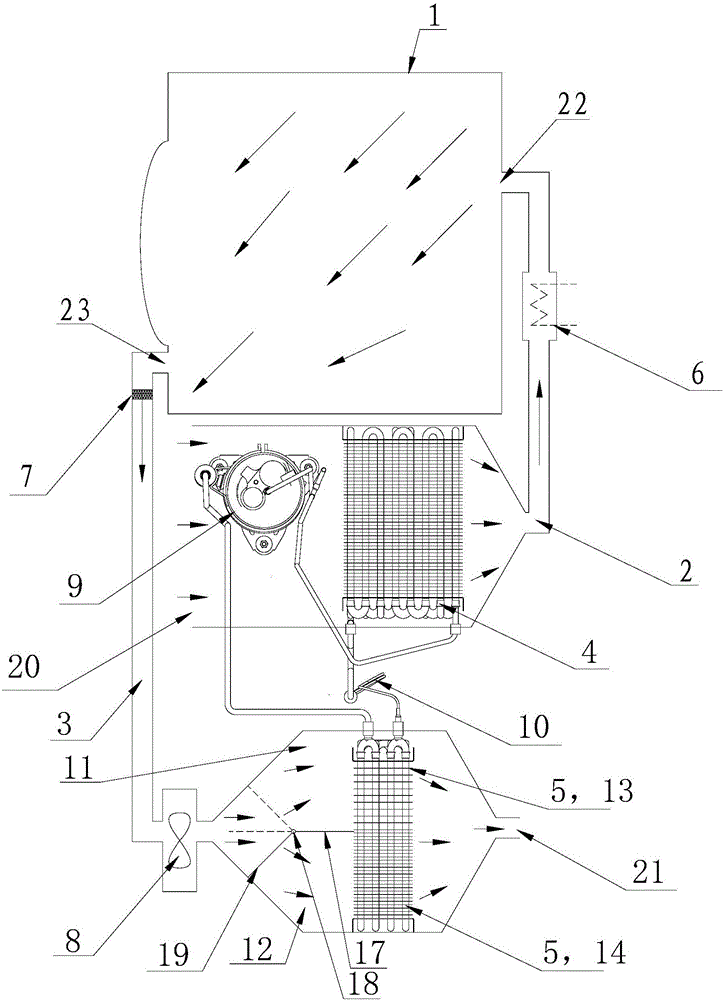
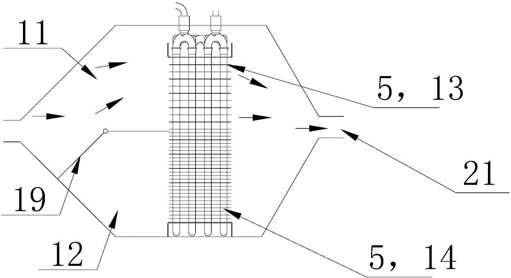
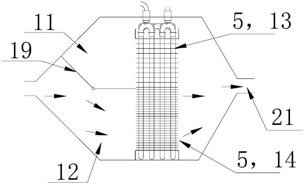
[0046] Such as figure 1 As shown, in this embodiment, a partition 17 is provided in the exhaust drying air passage 3 between the fan 8 and the air outlet 21, and the partition 17 extends in a direction parallel to the axis of the exhaust drying air passage 3 , so that the corresponding part of the exhaust drying air path 3 is divided into two corresponding parallel branches, which are respectively the first branch 11 and the second branch 12 .

[0047] In this embodiment, the evaporator 5 of the heat pump system is correspondingly arranged in the first branch 11 and the second branch 12 . The evaporator 5 extends in a direction perpendicular to the axis of the exhaust drying air path 3, and is arranged through the partition 17, so that the first part 13 of the evaporator 5 is arranged in the first branch 11, and the second part 14 is arranged in the first branch path 11. In the second branch 12. The evaporator 5 is arranged with a plurality of heat exchange fins arranged at ...

Embodiment 2

[0057] Such as Figure 5 As shown, the difference between this embodiment and the first embodiment above is that a first evaporator 15 is provided in the first branch 11 of the exhaust drying air passage 3, and a second evaporator 16 is provided in the second branch 12. . The density of the heat exchange fins provided on the first evaporator 15 is smaller than the density of the heat exchange fins provided on the second evaporator 16 .

[0058] In this embodiment, the air intake ends of the first evaporator 15 and the second evaporator 16 communicate with the throttling device 10 through a three-way control valve 25, and the first evaporator 15 and the second evaporator 16 The air outlet end communicates with the compressor 9 through another three-way control valve 25 . Therefore, the refrigerant medium can flow through the first evaporator 15 and the second evaporator 16 separately or simultaneously, so as to control the flow direction of the refrigerant.

[0059] The corr...

Embodiment 3

[0065] The difference between this embodiment and the above-mentioned second embodiment is that: one evaporator is provided in the first branch; at least two evaporators are provided in the second branch, so that the heat exchange fins of the evaporator in the first branch The fin density is smaller than the heat exchange fin density of the evaporator in the second branch (not indicated in the drawings).


PUM


Abstract

The invention relates to a straight-line heat-pump clothes dryer which comprises an outer barrel (1), an air drying wind path (2) and an exhaust drying wind path (3) which are used for communicating the outer barrel (1) with the exterior respectively. A heat-pump system is further arranged on the clothes dryer, a condenser (4) of the heat-pump system is arranged in the air drying wind path (2), and evaporators (5) are arranged on the exhaust drying wind path (3); the exhaust drying wind path (3) at least comprises two branches controllable in opening and closing, and the evaporators (5) are correspondingly and respectively arranged in the branches. By the arrangement that exhaust air flows flow through the different branches respectively or simultaneously at different drying stages of the clothes dryer, heat pump working status is adjusted reasonably, and drying efficiency of the clothes dryer is improved; meanwhile, the straight-line heat-pump clothes dryer is simple in structure, remarkable in effect and suitable for wide application.

Description

technical field [0001] The invention relates to a clothes drying device in the field of household appliances, in particular to a direct discharge heat pump clothes dryer. Background technique [0002] Existing dryers mainly exist in the following two ways: [0003] The first type is a straight-line clothes dryer, and its working principle is as follows: air is sucked in from the outside atmosphere, and the inhaled air is heated by a heating wire, and the heated high-temperature dry air is blown into the outer cylinder, and the clothes Moisture is vaporized; the vaporized water is mixed into the gas to become high-temperature moisture, and the high-temperature moisture is finally discharged out of the outer cylinder to achieve the purpose of drying clothes. However, in the above method, since the exhaust gas contains a large amount of waste heat, it cannot be recycled, resulting in high energy consumption and low efficiency. [0004] The second type is a heat pump dryer, an...

Claims


Application Information

Patent Timeline
IPC IPC(8): D06F58/20D06F58/22
CPCD06F58/206D06F58/24D06F58/30D06F58/10D06F2103/56D06F2105/26D06F2105/30D06F2103/08
Inventor 宋华诚许升田书君单世强
Owner QINGDAO HAIER DRUM WASHING MACHINE
Why Eureka
Try Eureka