Plate type heat exchanger liquid phase medium pressure drop testing system and testing method thereof

A technology of plate heat exchanger and test system, which is applied in the testing of machine/structural components, instruments, measuring devices, etc., can solve the problem of large pressure difference at the inlet of the flow channel, micro-deformation of heat exchange plates under pressure, and floor space. It can control the import pressure, ensure the achievability and save the investment effect.

Active Publication Date: 2017-03-08
HEFEI GENERAL MACHINERY RES INST +1
View PDF5 Cites 9 Cited by
  • Summary
  • Abstract
  • Description
  • Claims
  • Application Information

AI Technical Summary

Problems solved by technology

[0004] However, for users who only need to test the pressure drop, this type of test system includes a temperature control module, the process is relatively complicated, the investment cost is high, and the area is large; and in the actual test process, because the standard does not specify the pressure drop In the test plan, there are situations where the working medium on both sides flows into the plate heat exchanger sequentially, and the inlet pressure difference of the flow channels on both sides of the plate heat exchanger is relatively large, which causes the heat exchange plate to be slightly deformed under pressure, which affects the pressure drop of the plate heat exchanger. The test results had a non-negligible impact

Method used


Image

  • Plate type heat exchanger liquid phase medium pressure drop testing system and testing method thereof
  • Plate type heat exchanger liquid phase medium pressure drop testing system and testing method thereof

Examples


Embodiment 1

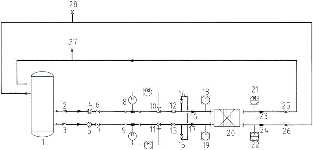
[0061] In this test scheme, the working fluids in the two channels (that is, the hot side channel and the cold side channel in the plate heat exchanger) connected to the first circulation loop and the second circulation loop of the plate heat exchanger 20 are equal Flow velocity, this test method includes the following steps:

[0062] S1, first open the shut-off valve 2, shut-off valve 3, open the first on-off valve 12, the second on-off valve 13, the third on-off valve 25, and the fourth on-off valve 26, and start the first variable frequency pump 4 and the second variable frequency pump 5 at low frequency , Fully open the first regulating valve 10 and the second regulating valve 11, and then open the first exhaust valve 27, the second exhaust valve 28, and close the first exhaust valve 27, after the exhaust gas is not condensed in the road system. The second exhaust valve 28; at this time, both the first balance valve 14 and the second balance valve 15 remain closed;

[0063] S2...

Embodiment 2

[0067] In this test scheme, the channel connecting the plate heat exchanger 20 with the first circulation loop, that is, the working fluid in the flow side channel, is in a flowing state, and the channel connecting the plate heat exchanger 20 with the second circulation loop is filled with liquid and pressure. The side channel is full of working fluid and the working fluid does not flow. The flow side channel of the plate heat exchanger 20 has the same working fluid hydraulic pressure as the fluid-filled pressure-maintaining side channel;

[0068] This test method includes the following steps:

[0069] S1, open the shut-off valve 2, open the first on-off valve 12, the third on-off valve 25, fully open the first regulating valve 10, open the first balance valve 14 and the second balance valve 15 to make the flow in the plate heat exchanger 20 The side channel is connected with the side channel filled with liquid and pressure; the first variable frequency pump 4 is started at low fre...

Embodiment 3

[0073] In this test scheme, the channel connecting the plate heat exchanger 20 with the first circulation loop, that is, the working fluid in the flow side channel is in a flowing state, and the channel connecting the plate heat exchanger 20 with the second circulation loop is the air-liquid normal pressure. The side channel is open to the atmosphere; this test method includes the following steps:

[0074] S1. Open the shut-off valve 2 in the first circulation loop, open the first on-off valve 12, the third on-off valve 25, fully open the first regulating valve 10, start the first variable frequency pump 4 at low frequency, and then open the first exhaust valve 27 After the exhaust system is not condensed, close the first exhaust valve 27; in this process, keep the shut-off valve 3, the second on-off valve 13, and the fourth on-off valve 26 on the second circulation loop closed , And disconnect the plate heat exchanger 20 from the second circulation loop. At this time, the air-li...


PUM


Abstract

The invention relates to a plate type heat exchanger liquid phase medium pressure drop testing system. The testing system comprises a tank and a plate type heat exchanger. A first circulating loop and a second circulating loop which are communicated with each other are arranged between the tank and the plate type heat exchanger. The first circulating loop is composed of a first circulating inlet liquid testing pipe segment and a first circulating outlet liquid testing pipe segment. The second circulating loop is composed of a second circulating inlet liquid testing pipe segment and a second circulating outlet liquid testing pipe segment. Each of the first circulating inlet liquid testing pipe segment and the second circulating inlet liquid testing pipe segment is provided with a working medium conveying module and a flow adjusting module. Four interfaces of the plate type heat exchanger and the circulating path are respectively provided with a pressure measuring module. The first circulating loop and the second circulating loop are respectively provided with an air exhausting module. The invention further provides three testing methods which match the testing system. The plate type heat exchanger liquid phase medium pressure drop testing system has advantages of simple structure, quick and convenient adjustment, and wide coverage testing range. The plate type heat exchanger liquid phase medium pressure drop testing system can effectively reduce effects of plate sheet deformation factors to a measurement result under a precondition that a pressure drop testing process requirement is satisfied.

Description

Technical field [0001] The invention belongs to the technical field of heat exchanger performance analysis and test control, and specifically relates to a plate heat exchanger liquid phase medium pressure drop test system and a test method thereof. Background technique [0002] The pressure drop caused by the flow resistance of the liquid phase medium in the plate heat exchanger is an important factor in judging the economic effect of its operation. The pressure drop test of the plate heat exchanger provides reliable data support for the development of new heat exchanger products and the determination of the power requirements of existing products in the process flow. With the wide application of large plate heat exchangers in the nuclear power field, the size of the plates is getting larger and thinner, and the micro-deformation of the plates in the actual test process has a greater impact on the test results. [0003] At present, the test system for the flow resistance of the li...

Claims


Application Information

Patent Timeline
Patent Type & Authority Applications(China)
IPC IPC(8): G01M99/00
CPCG01M99/00
Inventor 崔云龙张中清闫永超彭小敏何颜红张杰
Owner HEFEI GENERAL MACHINERY RES INST
Why Eureka
Try Eureka