Pulse laser emission circuit based on laser diode

A laser diode and transmitting circuit technology, applied in the field of laser measurement, can solve the problems of laser diode voltage drop reduction, narrow pulse waveform difficulty, peak power reduction, etc., and achieve the effects of reducing waveform oscillation, short switching time, and strong instantaneous power

Inactive Publication Date: 2017-03-08
NANJING UNIV OF SCI & TECH
View PDF3 Cites 16 Cited by
  • Summary
  • Abstract
  • Description
  • Claims
  • Application Information

AI Technical Summary

Problems solved by technology

Based on the design of the pulse laser emission circuit based on the laser diode, the circuit structure is simple and the theory is relatively sound. However, the laser diode is affected by the characteristics of the laser semiconductor and the distributed inductance and distributed capacitance of the drive circuit. It is very difficult to obtain a narrow pulse waveform with less oscillation and

Method used


Image

  • Pulse laser emission circuit based on laser diode
  • Pulse laser emission circuit based on laser diode
  • Pulse laser emission circuit based on laser diode

Examples


Embodiment Construction

[0015] It is easy to understand that, according to the technical solution of the present invention, those skilled in the art can imagine various implementations of the photodiode-based pulse emission circuit of the present invention without changing the essence of the present invention. Therefore, the following specific embodiments and drawings are only exemplary descriptions of the technical solution of the present invention, and should not be regarded as the entirety of the present invention or as a limitation or limitation on the technical solution of the present invention.

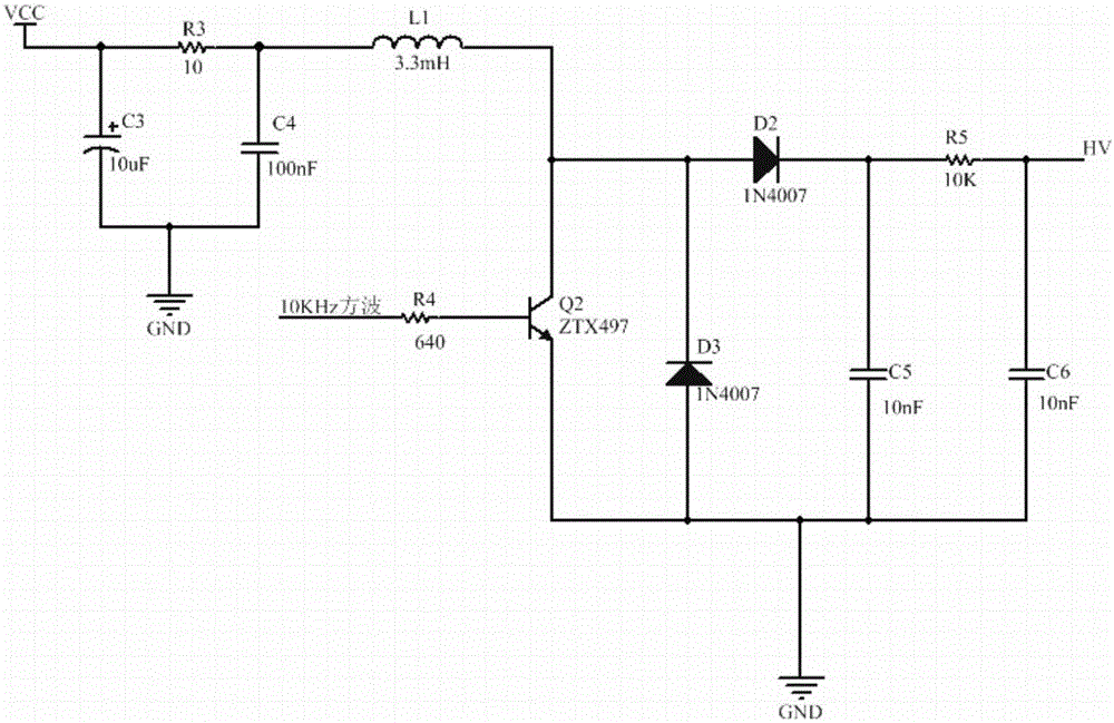
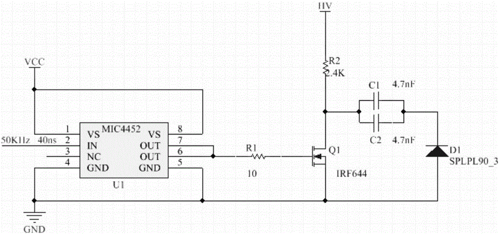
[0016] Taking the laser diode SPLPL90_3 as an example, the pulsed laser emitting circuit of the present invention includes a high-voltage generating circuit and a driving circuit of the laser diode SPLPL90_3, and the high-voltage generating circuit provides a high-voltage source for the driving circuit.

[0017] combine figure 1 , The high-voltage generating circuit of the laser diode SPLPL90_3 include...


PUM


Abstract

The invention provides a pulse laser emission circuit based on a laser diode. The pulse laser emission circuit comprises a high voltage generator circuit and a drive circuit of the laser diode, wherein the high voltage generator circuit is used for supplying a high voltage source for the drive circuit; the drive circuit is realized by using a printed circuit board, the distance between a current amplifying chip and a switch MOS tube is as long as possible, and a ground pin of the laser diode and a source level of the switch MOS tube are connected through a long and thin connecting line; and the lengths of connecting lines among the switch MOS tube, the laser diode, a first capacitor and a second capacitor are as short as possible. The pulse laser emission circuit realizes the emission of high repetition frequency narrow-pulse laser, so that the operating distance and precision of laser ranging are effectively improved.

Description

technical field [0001] The invention belongs to the field of laser measurement, and in particular relates to a laser diode-based pulsed laser emission circuit, which is applied in the fields of laser radar vehicle intelligent anti-collision, urban construction and planning, laser proximity fuze, laser active guidance and the like. Background technique [0002] Pulsed laser measurement uses a laser as a light source and a laser as a carrier. According to the time-of-flight principle, the distance is measured by detecting the time difference between the laser emission pulse and the laser echo pulse. It has the advantages of simple structure, low price, high reliability, and anti-interference It has the advantages of strong performance and no need for cooperative targets, and has been widely used in civilian and military applications. [0003] Realizing high repetition frequency and narrow pulse of laser is an important means to improve the working distance, dynamic detection a...

Claims


Application Information

Patent Timeline
IPC IPC(8): H01S5/042
Inventor 周玉蛟任侃孙爱娟王飞唐彦琴
Owner NANJING UNIV OF SCI & TECH
Why Eureka
Try Eureka