Optimal control for change conduction time of CRM boost PFC (Power Factor Correction) converter

A technology of on-time and optimal control, applied in the direction of high-efficiency power electronic conversion, output power conversion devices, electrical components, etc., can solve problems such as reducing computational complexity and system cost

Active Publication Date: 2017-03-08
NANJING UNIV OF AERONAUTICS & ASTRONAUTICS
View PDF7 Cites 16 Cited by
  • Summary
  • Abstract
  • Description
  • Claims
  • Application Information

AI Technical Summary

Problems solved by technology

[0004] The purpose of the invention is to solve the problem of v in greater than or less than V o / 2 These two cases need to be calculated separately for the complex calculation problems, and an optimized control method that can be realized by an analog control circuit or a digital controller is proposed. This method does not need to perform power detection and measurement of the effective value of the input voltage. Under any condition within the working range of the CRM boost PFC converter, the switch tube conduction time T on (t) The operation process is consistent, thereby reducing the operation complexity and system cost

Method used


Image

  • Optimal control for change conduction time of CRM boost PFC (Power Factor Correction) converter
  • Optimal control for change conduction time of CRM boost PFC (Power Factor Correction) converter
  • Optimal control for change conduction time of CRM boost PFC (Power Factor Correction) converter

Examples


Embodiment 1

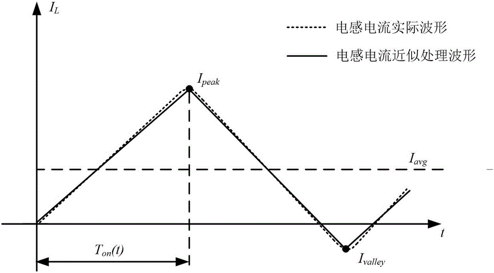
[0056] The optimal control of the change conduction time of the CRM step-up PFC converter of the present invention, under any condition within the working range of the CRM step-up PFC converter, the conduction time T of the switch tube on The operation process of (t) is consistent. Through the optimized control, the complexity of the entire control system can be reduced on the basis of reducing the input current THD of the CRM step-up PFC converter, thereby reducing the system cost. The optimal control adopted is based on the principle that the average current of the inductor in the CRM step-up PFC converter is equal to the sinusoidal reference current, and since the inductor current changes linearly in a switching cycle except for a very short resonance time, it can be The inductor current waveform is approximated as a triangle (see figure 2 ) to simplify the calculation of the average inductor current.

[0057] The optimized control of the CRM step-up PFC converter of the...

Embodiment 2

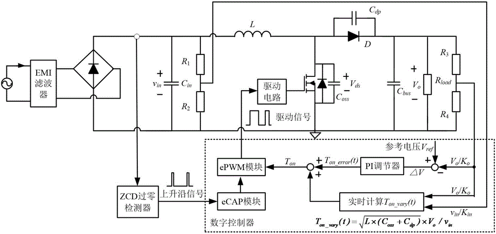
[0107] Embodiment 2: Based on the TMS320F28335 digital controller, realize the unified digital control method of the on-time operation optimization of the variable on-time control of the CRM Boost PFC converter

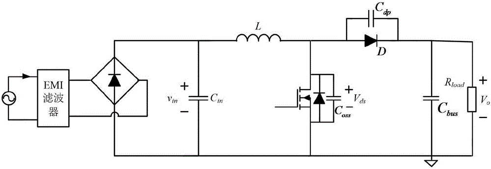
[0108] figure 1 It is the main circuit of CRM step-up PFC converter, including EMI filter, rectifier bridge, input capacitor, boost inductor, switch tube, diode, output capacitor and load. The circuit parameters of the CRM step-up PFC converter used in the example are: boost inductance L=230uH, parasitic capacitance C of the power device oss +C dp =80pF. The test conditions are: line frequency 50Hz, AC input voltage 110V and 220V, output bus voltage 400V, full load output power 200W. This example tests the input current THD against constant on-time control at 20%, 40%, 50%, 60%, 80% and 100% load respectively.

[0109] image 3 In order to realize the digital control circuit diagram of optimized unified control, in addition to the main circuit, a voltage sampling...

Embodiment 3

[0126] Embodiment 3: Realize the optimization and unification of the on-time operation of the variable on-time control of the CRM step-up PFC converter through analog circuit control

[0127] figure 1 It is the main circuit of CRM step-up PFC converter, including EMI filter, rectifier bridge, input capacitor, boost inductor, switch tube, diode, output capacitor and load. The circuit parameters of the CRM step-up PFC converter used in the example are: boost inductance L=230μH, parasitic capacitance C of the power device oss +C dp =80pF, the gain coefficient K of the multiplier M is 0.1 / V. The test conditions are: line frequency 50Hz, AC input voltage 110V and 220V, output bus voltage 400V, full load output power 200W.

[0128] Figure 5 Using the analog control method to realize the optimized and unified schematic diagram of the on-time operation of the variable on-time control of the CRM step-up PFC converter, including the voltage sampling circuit, the inductor current z...


PUM


Abstract

The invention discloses optimal control for change conduction time of a CRM boost PFC (Power Factor Correction) converter. By the optimal control, the unification of change conduction times under wide input voltage and variable load occasions can be achieved, and the problem of classification control complexity of two different situations with v<in> larger than or smaller than V<o> / 2 in a traditional method is avoided. Input and output voltage instantaneous values are sampled, corresponding real-time calculation or signal conditioning is performed, and thus, the conduction time of a switching tube is adjusted in real time to reduce the distortion of an input current; and a constant part of the conduction time is adjusted by a voltage PI (Proportion Integral) ring, and a variable part is obtained through calculation by a digital controller according to a unified algorithm or is adjusted in real time by an external circuit such as an analog divider. Effective values of an output power and an input voltage are not needed to detect and are not needed to input into a voltage phase locking circuit, the control on the change conduction time of the converter under an arbitrary condition in a working range is achieved by a normalization control method, so that the circuit cost is substantially reduced, and the control difficulty is substantially reduced.

Description

technical field [0001] The invention relates to the power converter technology, in particular to an optimization control applied to the change conduction time of a CRM step-up PFC converter. Background technique [0002] The wide application of power electronic devices has brought a lot of harmonic pollution to the power grid, seriously affecting the power supply quality of the power grid and the normal operation of other electrical equipment. In order to reduce the harmonic pollution caused by power electronic devices and meet the harmonic standard IEC61000-3-2 formulated by the International Electrotechnical Commission, it is necessary to use power factor correction (Power FactorCorrection, PFC) converters to suppress harmonic components so that various electrical equipment achieve the required harmonic standards. Among them, the CRM step-up PFC converter is widely used due to its high power factor, small size, light weight and low cost. [0003] The variable conduction ...

Claims


Application Information

Patent Timeline
Patent Type & Authority Applications(China)
IPC IPC(8): H02M1/42H02M1/12
CPCH02M1/12H02M1/4225H02M1/0012Y02B70/10
Inventor 任小永吴羽郭哲辉陈乾宏张之梁
Owner NANJING UNIV OF AERONAUTICS & ASTRONAUTICS
Why Eureka
Try Eureka