
A medium-high temperature flue gas circulation type low-nitrogen staged burner and its process

A staged combustion and flue gas circulation technology, applied in the direction of gas fuel burners, burners, combustion types, etc., can solve the problems of reducing nitrogen oxide production, large footprint, and size restrictions, so as to avoid tempering, reduce The effect of a small footprint

Active Publication Date: 2019-06-11
TONGJI UNIV
View PDF8 Cites 0 Cited by
  • Summary
  • Abstract
  • Description
  • Claims
  • Application Information

AI Technical Summary

Problems solved by technology

The internal circulation of the flue gas is mainly to entrain the high-temperature flue gas near the flame through the high-speed jet in the burner, reduce the oxygen concentration of the combustion-supporting air in the furnace or dilute the concentration of combustible components of the gas, thereby reducing the production of nitrogen oxides; but because Due to the size limitation, the entrainment volume of the smoke and the mixing effect with the air are not very ideal
Flue gas external circulation uses fans to send low-temperature flue gas from the boiler outlet to the burner for mixing. Additional facilities such as flue gas pipes, induced draft fans, and flue gas regulating baffles are required, which faces high costs and large floor space. And other issues
At the same time, the mixture of entrained low-temperature flue gas and combustion-supporting air will increase the instability of the flame

Method used


Image

  • A medium-high temperature flue gas circulation type low-nitrogen staged burner and its process

Examples


Embodiment 1

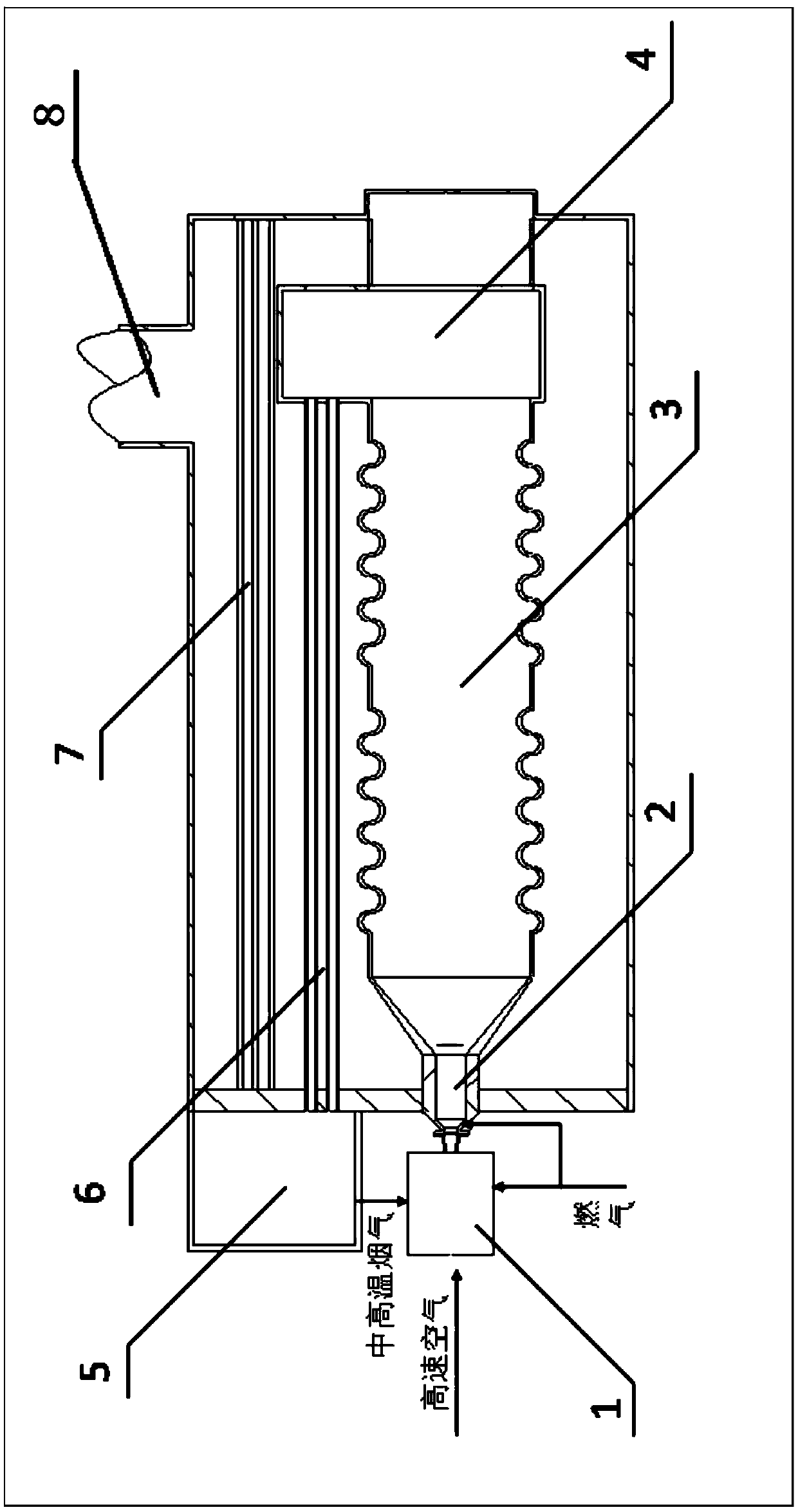
[0022] A medium-high temperature flue gas circulation type low-nitrogen staged burner, its structure is as follows figure 1 As shown, the high-temperature flue gas circulation low-nitrogen staged burner in this embodiment is in the form of a horizontal gas boiler, and the burner includes a staged burner body, an air-flue gas mixing chamber 1 arranged at the front end of the staged burner body, The rear smoke return chamber 4 arranged at the rear end of the staged burner body, the front smoke return chamber 5 communicated with the rear smoke return chamber 4 through the return pipe 6 and the flue gas outlet 8, the front smoke return chamber 5 communicates with the air-flue gas mixing chamber 1, And the front smoke return chamber 5 communicates with the smoke outlet 8 through the smoke outlet pipe 7;

[0023] This embodiment specifically includes the technology of using medium-high temperature flue gas to heat combustion-supporting air, the technology of using high-speed air to ...


PUM


Abstract

The invention relates to a medium-high temperature flue gas circulation type low-nitrogen graded burner which comprises a graded burner body, an air and flue gas mixing cavity, a rear smoke return chamber, a front smoke return chamber and a smoke outlet. The air and flue gas mixing cavity is arranged at the front end of the graded burner body, the rear smoke return chamber is arranged at the rear end of the graded burner body, and the front smoke return chamber is made communicated with the rear smoke return chamber through a return pipe. The front smoke return chamber is made communicated with the air and flue gas mixing cavity, and the front smoke return chamber is made communicated with the smoke outlet through a smoke outlet pipe. Compared with the prior art, the temperature of combustion-supporting air is remarkably improved, the oxygen concentration in combustion-supporting air is reduced, and the nitric oxide produced through burning can be reduced. The technology that medium-high temperature flue gas is entrained through high-speed air is utilized for avoiding the phenomenon that a flue gas pipeline and a high-temperature induced draft fan are separately arranged, equipment is simplified, and the production cost of the burner is reduced; and by utilizing the technology that high-speed high-temperature low-oxygen air is matched with the air and fuel gas graded burner to achieve diffuse burning, the concentration of the nitric oxide produced through high-temperature burning is remarkably reduced.

Description

technical field [0001] The invention relates to the technical field of low-nitrogen combustion of industrial boilers, in particular to a medium-high temperature flue gas circulation type low-nitrogen graded burner and a process. Background technique [0002] With the release of Beijing's local standard "Emission Standard of Air Pollutants for Boilers" DB 11 / 139-2015, areas represented by Beijing have become more stringent on the emission of nitrogen oxides from industrial boilers, and it is difficult for existing burners to meet the stringent requirements. Pollutant discharge requirements. Therefore, the use of ultra-low nitrogen burners is one of the most direct and effective solutions for industrial boilers to solve nitrogen oxide emissions. [0003] At present, the control of nitrogen oxides on the burner side is mainly through air classification, gas classification, and flue gas recirculation. Using air or gas classification alone has limited effect, and the ratio of p...

Claims


Application Information

Patent Timeline
Patent Type & Authority Patents(China)
IPC IPC(8): F23D14/02F23D14/66F23C9/00F23L15/00
CPCF23C9/00F23D14/02F23D14/66F23L15/00Y02E20/34
Inventor 朱彤宗超
Owner TONGJI UNIV
Learn More