On-chip modulation integrated optical resonant cavity

An optical resonant cavity and integrated optics technology, applied in the fields of optical communication and inertial navigation, can solve problems such as the inability to greatly improve the degree of integration, influence, and stability limitations of the system integration system, so as to enhance system reliability and simplify the system model , The effect of reducing system size and power consumption

Inactive Publication Date: 2017-03-15
BEIHANG UNIV
View PDF3 Cites 7 Cited by
  • Summary
  • Abstract
  • Description
  • Claims
  • Application Information

AI Technical Summary

Problems solved by technology

The difference in the material of the modulator, resonant cavity and fiber coupling point becomes an important limiting factor that the integration of the entire gyroscope system cannot be greatly improved
like figure 1 As shown in , the place marked with a cross in the figure is the fiber coupling point, and the optical fiber used for connection between the fiber coupling point and the coupling point has brought restrictions and influences on system integration and system stability.

Method used


Image

  • On-chip modulation integrated optical resonant cavity
  • On-chip modulation integrated optical resonant cavity
  • On-chip modulation integrated optical resonant cavity

Examples


Embodiment Construction

[0018] The present invention will be further described in detail with reference to the accompanying drawings and embodiments.

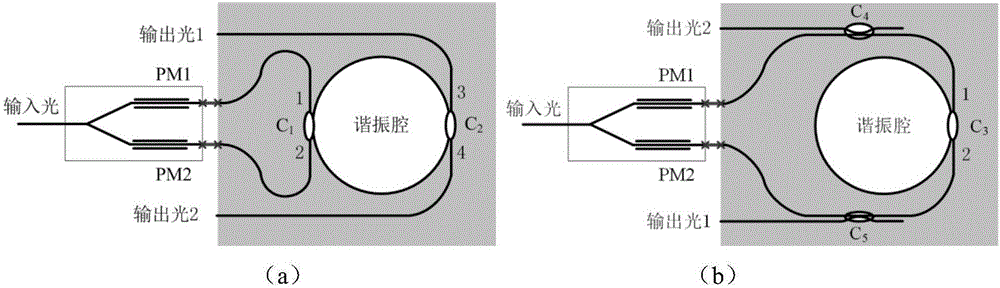
[0019] The invention provides an on-chip modulated integrated optical resonant cavity, which is suitable for applying the resonant cavity as an optical path system of a sensor / filter. The lithium niobate phase modulator is directly fabricated on the upper layer of the resonant cavity, which is the key device to realize the frequency locking of the resonant cavity; at the same time, the lithium niobate waveguide modulator outside the cavity realizes the modulation of the optical frequency entering the cavity, providing data reference for frequency locking.

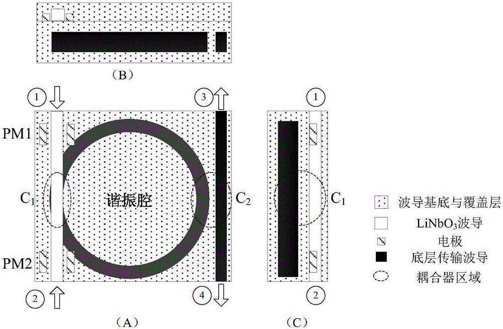
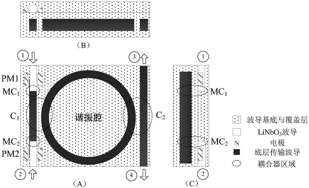
[0020] The transmissive structure of the on-chip modulated integrated optical resonant cavity provided by the present invention is an integrated upper and lower two-layer structure, and the lithium niobate waveguide modulator is made on the upper layer of the resonant cavity. A resonant cavity and ...


PUM


Abstract

The invention provides an on-chip modulation integrated optical resonant cavity, which is applied to a multilayer wave guide structure, and realizes the high-degree integration design of active and passive devices of the integrated optical resonant cavity. The integrated optical resonant cavity provided by the invention is of an integrated two-layer structure including an upper layer and a lower layer; the resonant cavity and transmission wave guide are prepared on the waveguide substrate of the lower layer; a lithium niobate waveguide modulator is manufactured at the upper layer of the resonant cavity and exerts an electric field at the two sides of the lithium niobate waveguide; the effective refractive index of the waveguide is changed; the optical phase delay quantity modulation in the waveguide is realized. A cross-layer coupler is prepared between the lithium niobate waveguide and the resonant cavity or transmission waveguide positioned at the lower layer. The optical fiber coupling structure of the external modulator and the resonant cavity is omitted; the modulator and the resonant cavity are vertically and directly coupled; the attenuation of the cavity-entering light polarization extinction ratio can be reduced, so that higher cavity-entering light polarization extinction ratio can be maintained; the system model is simplified; the system integration degree is improved; the system reliability is enhanced.

Description

technical field [0001] The invention is an on-chip modulated integrated optical resonant cavity, which uses a multilayer waveguide structure to realize the highly integrated design of the active and passive components of the integrated optical resonant cavity, and can be applied to the technical fields of optical communication and inertial navigation. Background technique [0002] Currently, an external phase modulator is mostly used to control the signal in the optical waveguide resonator, such as figure 1 The split structure shown. The light emitted by the light source is divided into two identical beams by a beam splitter. The light in the counterclockwise direction (CCW) passes through the modulator PM1 to adjust the transmitted light, and then enters the resonant cavity. Through the transmission coupling of the resonant cavity, it is output from the other input end. Similarly, the clockwise light (CW) passes through PM2, adjusts the transmitted light, passes through ...

Claims


Application Information

Patent Timeline
Patent Type & Authority Applications(China)
IPC IPC(8): G02F1/035
CPCG02F1/035
Inventor 冯丽爽王潇刘丹妮杨聚朋焦洪臣王琪伟
Owner BEIHANG UNIV
Why Eureka
Try Eureka