High-voltage generator and photoelectric detection device

A high-voltage generator and pulse generating circuit technology, applied in the field of high-voltage switching power supply, can solve the problems of unstable analysis data, unstable output voltage of high-voltage generator, etc.

Active Publication Date: 2017-03-15
昆山书豪仪器科技有限公司 +1
View PDF10 Cites 2 Cited by
  • Summary
  • Abstract
  • Description
  • Claims
  • Application Information

AI Technical Summary

Problems solved by technology

[0005] In view of this, the embodiment of the present invention provides a high-voltage generator and a photoelectric detection device to solve the instability of the output voltage of the existing high-voltage generator, and then using the existing high-voltage generator as the power supply of the analysis instrument will cause the analysis data to be inconsistent. stability problem

Method used


Image

  • High-voltage generator and photoelectric detection device
  • High-voltage generator and photoelectric detection device
  • High-voltage generator and photoelectric detection device

Examples


Embodiment 1

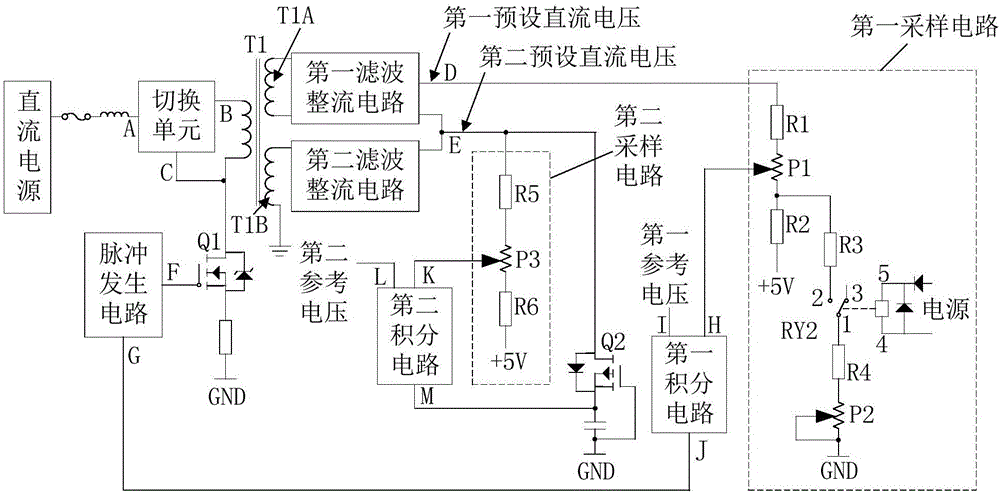
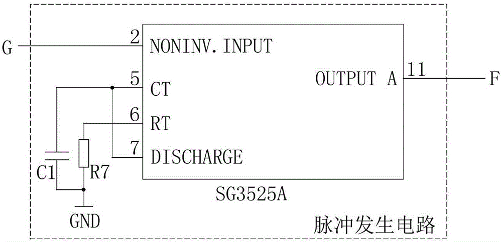
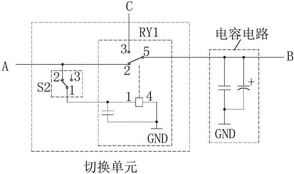
[0033] figure 1 A functional block diagram of a high voltage generator according to an embodiment of the invention is shown. according to figure 1As shown, the high voltage generator includes a transformer T1, a first controllable switch Q1, a pulse generating circuit, a first filtering and rectifying circuit and a second filtering and rectifying circuit.

[0034] Such as figure 1 As shown, one end of the primary side of the transformer T1 is connected to a DC power source, such as a 24V DC voltage source. Such as Figure 5 As shown, the secondary side of the transformer T1 includes a first winding T1A and a second winding T1B, one end of the first winding T1A is connected to one end of the second winding T1B; the other end of the second winding T1B is grounded.

[0035] The two ends of the controlled switch of the first controllable switch Q1 are connected in series with the primary circuit of the transformer T1 for controlling the connection or disconnection of the prima...

Embodiment 2

[0071] An embodiment of the present invention provides a photodetection device, which includes the high-voltage generator described in Embodiment 1 or any optional manner in Embodiment 1, an attenuation plate, and a plurality of photomultiplier tubes.

[0072] Figure 8 A schematic diagram of the connection of the photodetection device according to the embodiment of the present invention is shown. Such as Figure 8 As shown, the attenuation board consists of multiple resistors connected in series, such as Figure 8 Middle R81 to R814, and short wire. One end of the plurality of resistors connected in series is connected to the first preset DC voltage output end of the high voltage generator. Connection ports are left between adjacent resistors, such as Figure 8 Ports 1 to 16 in . The two ends of the short-circuit wire are respectively used to connect to the connection ports on the attenuation board.

[0073] Multiple photomultiplier tubes, such as Figure 8 In the phot...


PUM


Abstract

The invention discloses a high-voltage generator and a photoelectric detection device. The high-voltage generator comprises a transformer, a first controllable switch, a pulse generation circuit, a first rectifier and filter circuit and a second filter and rectifier circuit, wherein one end of a primary side of the transformer is connected with a DC power supply, a secondary side comprises a first winding and a second winding, one end of the first winding is connected with one end of the second winding and the other end of the second winding is grounded; two ends of a controlled switch of the first controllable switch are connected to a primary side loop of the transformer in series; the pulse generation circuit is used for generating a pulse signal with a preset frequency; the pulse generation circuit is connected with a control terminal of the first controllable switch; the first filter and rectifier circuit is used for filtering and rectifying boosted voltage and then outputting first preset DC voltage; and the second filter and rectifier circuit is used for filtering and rectifying the boosted voltage and then outputting second preset DC voltage. According to the high-voltage generator disclosed by the invention, stable first preset DC voltage and second preset DC voltage can be simultaneously provided.

Description

technical field [0001] The invention relates to the technical field of high-voltage switching power supplies, in particular to a high-voltage generator and a photoelectric detection device. Background technique [0002] High voltage generator (English: High voltage power supply), also known as high voltage power supply, is used to provide high voltage for other equipment, such as X-ray machine high voltage power supply, laser high voltage power supply, spectral analysis high voltage power supply, nondestructive testing high voltage power supply, semiconductor manufacturing equipment High-voltage power supply, high-voltage power supply for capillary electrophoresis, high-voltage power supply for non-destructive testing, high-voltage power supply for particle injection in semiconductor technology, high-voltage power supply for physical vapor deposition (PVD), high-voltage power supply for nanolithography, etc. Low ripple is an important research direction for high-voltage gene...

Claims


Application Information

Patent Timeline
Patent Type & Authority Applications(China)
IPC IPC(8): H02M3/335H02M1/14
CPCH02M1/14H02M3/33561H02M3/33576
Inventor 徐荣网耿建峰吴仁贵
Owner 昆山书豪仪器科技有限公司
Why Eureka
Try Eureka