

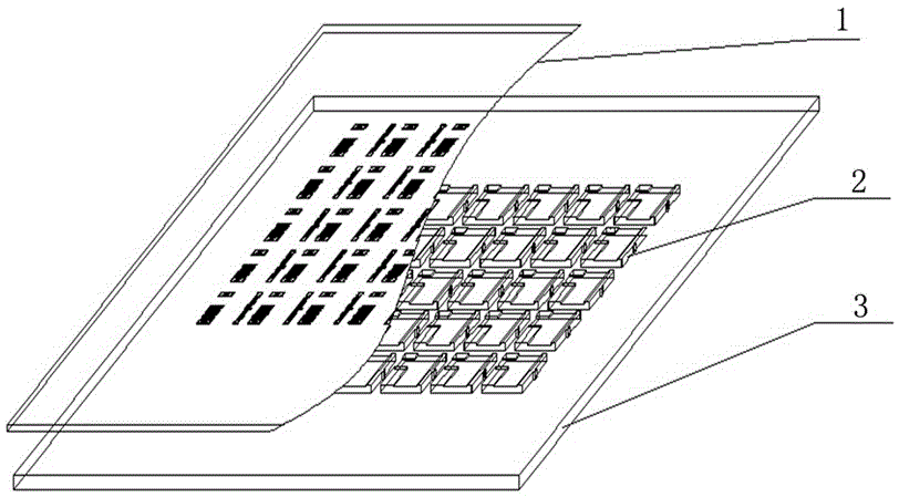
Machining method for soldering micro-strip boards by using printing solder paste
A processing method and technology of microstrip plate, applied in metal processing equipment, manufacturing tools, welding equipment and other directions, to achieve the effect of improving efficiency, simple operation and reducing processing cost
- Summary
- Abstract
- Description
- Claims
- Application Information
AI Technical Summary
Problems solved by technology
Method used
Image

Examples
Embodiment 1
[0042] Materials used: 1. Solder paste (alpha LR721H3), 2. Absolute ethanol (CH3CH2OH), 3. Dust-free cloth, 4. Anti-static gloves.
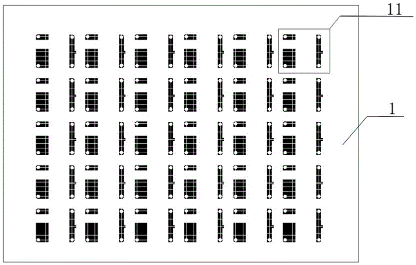
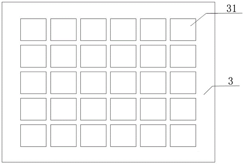
[0043] Equipment and tools: 1. Stainless steel scraper (length 200mm), 2. Stencil (370*470mm), 3. Printing platform, 4. Positioning bottom plate, 5. Stirring rod, 6. Solder paste mixer, 7. Ultrasonic cleaner, 8. Reflow oven (VXS374), 9. Thermometer (DATAPAQ / 9000), 10. X-ray detector (Y.Cougar SMT).
[0044] Preparation:
[0045] Take out the stored solder paste from the refrigerator, check the type and expiration date of the solder paste, and stir it with a solder paste mixer: warm it up at room temperature for more than 2 hours before stirring, and stir for 15 minutes.
[0046] Before printing solder paste, use a non-woven cloth to dip an appropriate amount of absolute ethanol to clean the stencil 1. Squeegee, and place them in categories.
[0047] The specific processing steps of the brazed microstrip plate are as follows:
[0048] (1) Clean...
PUM
| Property | Measurement | Unit |
|---|---|---|
| thickness | aaaaa | aaaaa |
| width | aaaaa | aaaaa |
| thickness | aaaaa | aaaaa |
Abstract
Description
Claims
Application Information