Rectifying the carbon fiber composite material profile and its preparation method

A composite material and carbon fiber technology, applied in the field of fairings, can solve the problems of reduced bonding fastness, corrosion of water leakage holes, and inability to completely limit water immersion into the cloth, so as to improve the bonding fastness and prevent lightning strikes.

Active Publication Date: 2019-07-02
ANHUI JIALIQI AEROSPACE CARBON FIBER CO LTD
View PDF6 Cites 0 Cited by
  • Summary
  • Abstract
  • Description
  • Claims
  • Application Information

AI Technical Summary

Problems solved by technology

However, since corrosion does not only occur on the outer surface of the fairing, corrosion may still occur on the inner wall of the leak hole
[0008] However, in the prior art, it is impossible to cover the smooth water retaining cloth on the inner wall of the water leakage hole and the outside of the water leakage hole at the same time.
For example, if you first ensure that the water retaining cloth on the inner wall of the leak hole is flat, then when smoothing the water retaining cloth on the outside of the leak hole, the water retaining cloth just glued to the inner wall of the leak hole will be peeled off due to external force, so that the water retaining cloth and the inner wall of the leak hole will be separated. There is a hollow area similar to bubbling between the inner walls of the leak hole or cracks at the edge of the joint between the water retaining cloth and the inner wall of the leak hole, resulting in a decrease in the bonding fastness between the two, and the water retaining cloth is easy to fall off
In addition, although the water-retaining cloth can play a waterproof role, the fabric structure of the cloth, such as plain weave, twill weave, satin weave, warp knitting, and weft knitting, determines that it has gaps, which cannot completely restrict water from immersing in the cloth. After the water is submerged and enters the hollow area, it will stay in the hollow layer area for a long time and corrode the material

Method used


Image

  • Rectifying the carbon fiber composite material profile and its preparation method
  • Rectifying the carbon fiber composite material profile and its preparation method
  • Rectifying the carbon fiber composite material profile and its preparation method

Examples


Embodiment 1

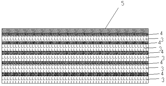
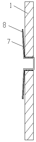
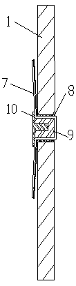
[0039] Such as Figure 1-2 As shown, this embodiment discloses a carbon fiber composite material profile for a fairing, which includes a carbon fiber composite material profile body 1 , and a water leakage hole is opened on the carbon fiber composite material profile body 1 . The carbon fiber composite profile body 1 is made of carbon fiber composite material. The carbon fiber composite material includes several layers of carbon fiber layers 3 , several layers of resin base layers 4 , and one layer of copper mesh layer 5 . The copper mesh layer 5, the resin base layer 4, and the carbon fiber layer 3 are arranged alternately from the outside to the inside. The copper mesh layer 5 is located in the outermost layer, and of course the carbon fiber layer 3 or the resin base layer 4 can be located in the innermost layer. If the carbon fiber layer 3 is located in the outermost layer, the outermost carbon fiber layer 3 is single-layer dipped in glue.

[0040] The outside of the lea...

Embodiment 2

[0055] This embodiment discloses a method for preparing the above-mentioned carbon fiber composite profile for a fairing, comprising the following steps:

[0056] (1) Glue dipping: dip five pieces of polyacrylonitrile-based activated carbon fiber cloth into the glue solution of epoxy resin glue. Wherein the mass ratio of epoxy resin and dicyandiamide curing agent in the epoxy resin glue solution is 1:1.

[0057] (2) Laying up: polyacrylonitrile-based activated carbon fiber cloth and a layer of copper mesh are laminated sequentially on the mold to ensure that the copper mesh is located on the outermost layer; the resin base layer and the carbon fiber layer are arranged under the copper mesh layer and arranged alternately in sequence ;

[0058] (3) Vacuuming: place the laminated composite material in step (2) in a vacuum environment, and vacuumize to 1.0E-3Pa.

[0059] (4) Shaping: Treat the composite material in step (3) at 200° C. and a pressure of 5 atmospheres for 2 hours....

Embodiment 3

[0063] This embodiment discloses a method for preparing the above-mentioned carbon fiber composite profile for a fairing, comprising the following steps:

[0064] (1) Glue dipping: Put three pieces of pitch-based activated carbon fiber felt and two pieces of viscose-based activated carbon fiber felt into the epoxy resin glue. The mass ratio of epoxy resin to DDS curing agent in the epoxy resin glue solution is 1:0.9.

[0065] (2) Laying: Lay three pieces of pitch-based activated carbon fiber mats, two pieces of viscose-based activated carbon fiber mats, and a layer of copper mesh on the mold in order to ensure that the copper mesh is located in the outermost layer; the resin base layer and the carbon fiber layer are set It is set under the copper mesh layer and arranged in a staggered order.

[0066] (3) Vacuuming: place the laminated composite material in step (2) in a vacuum environment, and vacuumize to 3.0E-3Pa.

[0067] (4) Shaping: process the composite material in ste...


PUM


Abstract

The invention discloses a carbon fiber composite profile used for a fairing. The carbon fiber composite profile comprises a carbon fiber composite profile body which is provided with a water drain hole. A carbon fiber composite comprises a plurality of carbon fiber layers, a plurality of resin base layers and a copper net layer. The copper net layer, the resin base layers and the carbon fiber layers are arranged sequentially from outside to inside. Water stopping cloth covers the outer side of the water drain hole and flatly attached to the periphery of the outer side of the water drain hole and the inner wall of the water drain hole in a glued mode. The invention further discloses a preparation method for the carbon fiber composite profile used for the fairing. The carbon fiber composite profile used for the fairing and the preparation method for the carbon fiber composite profile have the advantages that electrostatic focusing is prevented, lightning attachment points and a traditional carbon fiber composite profile are integrally formed, and corrosion phenomena on the periphery and the inner wall of the water drain hole are rapidly and efficiently avoided.

Description

technical field [0001] The invention relates to the technical field of fairings, in particular to a carbon fiber composite profile for a fairing and a preparation method thereof. Background technique [0002] Fairings are used to protect satellites and other payloads from harmful environments such as aerodynamics, aerodynamic heating, and acoustic vibrations. [0003] The fairing of the prior art prevents static electricity concentration by flame-spraying aluminum on its surface. However, this method is easy to pollute, and the price of aluminum is high, and the fairing after flame spraying aluminum is heavy. [0004] Patent application 201620136405.2 discloses an aircraft tail fairing, which uses copper mesh to increase lightning attachment points. Copper itself has good electrical conductivity, and the price is relatively cheap, and this method is also pollution-free. However, the patent directly lays the copper mesh on the surface of the fairing, which is troublesome t...

Claims


Application Information

Patent Timeline
Patent Type & Authority Patents(China)
IPC IPC(8): B64C7/00B32B9/00B32B5/02B32B9/04B32B5/26B32B15/18B32B15/02B32B27/04B32B3/08B32B7/08B32B33/00B32B37/10B32B37/06B32B38/04B29C70/34
CPCB29C70/34B32B5/26B32B7/08B32B33/00B32B37/06B32B37/10B32B38/04B32B2250/20B32B2260/021B32B2260/046B32B2262/103B32B2262/106B32B2307/21B32B2605/18B64C7/00Y02T50/40
Inventor 梁禹鑫路强何小平康彦龙
Owner ANHUI JIALIQI AEROSPACE CARBON FIBER CO LTD
Why Eureka
Try Eureka