Welded stirrup steel framework beam/pillar

A technology of stirrups and steel bars, applied in the directions of columns, piers, pillars, etc., can solve the problems of complicated binding of steel meshes and difficult construction at nodes, so as to save the formwork, reduce the amount of steel reinforcement works, and shorten the construction time. Effect

Inactive Publication Date: 2017-03-22
SHANDONG UNIV
View PDF7 Cites 6 Cited by
  • Summary
  • Abstract
  • Description
  • Claims
  • Application Information

AI Technical Summary

Problems solved by technology

However, the vertical steel bars and stirrups have not been canceled, and there are still problems of complicated binding of steel mesh and difficult construction at joints

Method used


Image

  • Welded stirrup steel framework beam/pillar
  • Welded stirrup steel framework beam/pillar
  • Welded stirrup steel framework beam/pillar

Examples


Embodiment 1

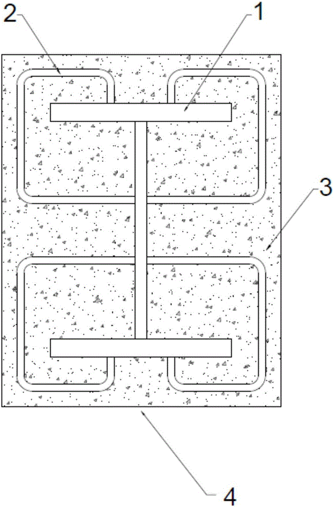
[0042] like figure 1 As shown, the welded stirrup-steel-reinforced concrete member 4 includes steel frame and stirrups, and stirrups are welded outside the steel frame, and concrete 3 is poured inside and outside the space formed by the stirrups and the steel frame; The steel frame is I-shaped, and the left side of the I-shaped steel frame 1 is welded with a C-shaped stirrup 2 connecting its top and its vertical rod part and a C-shaped stirrup 2 connecting its bottom and its vertical rod part. ; On the right side of the I-shaped steel frame 1, a C-shaped stirrup connecting its top and its vertical rod part and a C-shaped stirrup connecting its bottom and its vertical rod part are welded.

[0043] A left-right and up-down symmetrical structure is formed between the I-shaped steel frame and the stirrup.

Embodiment 2

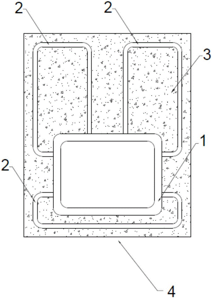
[0045] like figure 2 As shown, the welded stirrup-steel-reinforced concrete member 4 includes steel frame and stirrups, and stirrups are welded outside the steel frame, and concrete 3 is poured inside and outside the space formed by the stirrups and the steel frame; The steel frame 1 is a closed rectangular structure, and a C-shaped stirrup 2 is welded to the bottom of the rectangular structure, and the C-shaped stirrup 2 connects the left and right sides of the rectangular structure; the top of the rectangular structure is welded with two symmetrically distributed C-shaped stirrups 2, one C-shaped stirrup 2 connects the top and the left side of the rectangular structure; another C-shaped stirrup 2 connects the top and the right side of the rectangular structure. A left-right symmetrical structure is formed between the I-shaped steel frame and the stirrup.

[0046] The rectangular structure described here is a rectangular structure with four corners transitioning through arcs,...

Embodiment 3

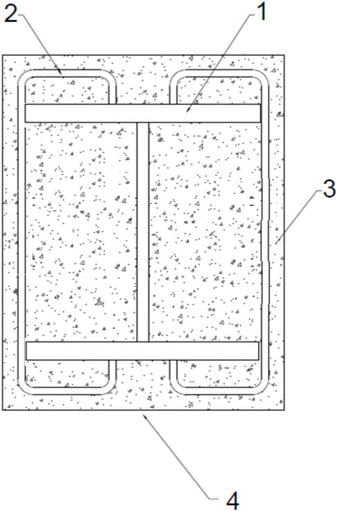
[0048] like image 3 As shown, the welded stirrup-steel-reinforced concrete member 4 includes steel frame and stirrups, and stirrups are welded outside the steel frame, and concrete 3 is poured inside and outside the space formed by the stirrups and the steel frame; The steel frame 1 is I-shaped, and a C-shaped stirrup 2 is welded on the left side of the I-shaped steel frame to connect its top and its bottom; C-shaped stirrups at the bottom 2.

[0049] A left-right and up-down symmetrical structure is formed between the I-shaped steel frame and the stirrup.


PUM


Abstract

The invention relates to the field of civil engineering structures, in particular to a welded stirrup-steel framework concrete component. The welded stirrup-steel framework concrete component is a combined structure component formed by welding stirrup on a steel framework and pouring concrete, and shear connectors and longitudinal steel reinforcements of a traditional steel framework concrete component are reduced. Due to the fact that the steel framework is wrapped with the concrete, structural stiffness and shear capacity are improved, and earthquake resistance can be improved remarkably. The steel framework has bearing capacity to a certain extent and is used for bearing loads in the construction stage, a formwork is suspended on the steel framework, formwork erection is omitted, and assembly line production is facilitated. The stirrup in the welded stirrup-steel framework concrete component can improve the crack resistance of the concrete on the one hand, and can be used as a shear part on the other hand, cooperative work of the steel framework and the concrete is ensured, the construction process is simplified, the steel reinforcement net rack binding process is omitted, the manufacturing time is shortened, and industrialized production of components is facilitated.

Description

technical field [0001] The invention relates to the field of civil engineering structures, in particular to a welded stirrup-steel-reinforced concrete member. Background technique [0002] Ordinary steel-concrete columns consist of steel, concrete, studs welded to the surface of the steel, longitudinal reinforcement and stirrups. Longitudinal steel bars and stirrups are bound to form a steel frame, the steel frame and the welded studs on the steel frame surface are manufactured and welded in the factory; the steel frame composed of longitudinal steel bars and stirrups is processed on site; then the formwork is installed and concrete is poured. At the reinforced concrete beam-column joint, in order to facilitate the passage of longitudinal reinforcement and stirrup, it is necessary to drill holes in the flange and web of the steel frame. The construction process includes not only the construction and installation of the steel structure, but also the reinforcement engineering...

Claims


Application Information

Patent Timeline
Patent Type & Authority Applications(China)
IPC IPC(8): E04C3/32E04C3/34E04C3/293
CPCE04C3/32E04C3/293E04C3/34
Inventor 王培军李阳娄超乌拉托亚
Owner SHANDONG UNIV
Why Eureka
Try Eureka