Automatic reversing water pump

An automatic reversing and water pump technology, applied in pump control, machine/engine, liquid variable capacity machinery, etc., can solve the problems of inability to provide electrical system drive power, complex water pump system, etc., and achieve light weight, simple implementation, and high performance. The effect of low consumption

Inactive Publication Date: 2017-03-22
湖南莫尔顿智能勘探机器人有限公司
View PDF5 Cites 19 Cited by
  • Summary
  • Abstract
  • Description
  • Claims
  • Application Information

AI Technical Summary

Problems solved by technology

Feedback through the position signal at the end of the stroke is a solution. The position signal can be realized through an external travel switch or proximity switch, but the external travel switch or proximity switch needs to be processed by the electrical system, which complicates the pump system. , and many w

Method used


Image

  • Automatic reversing water pump
  • Automatic reversing water pump

Examples


Embodiment 1

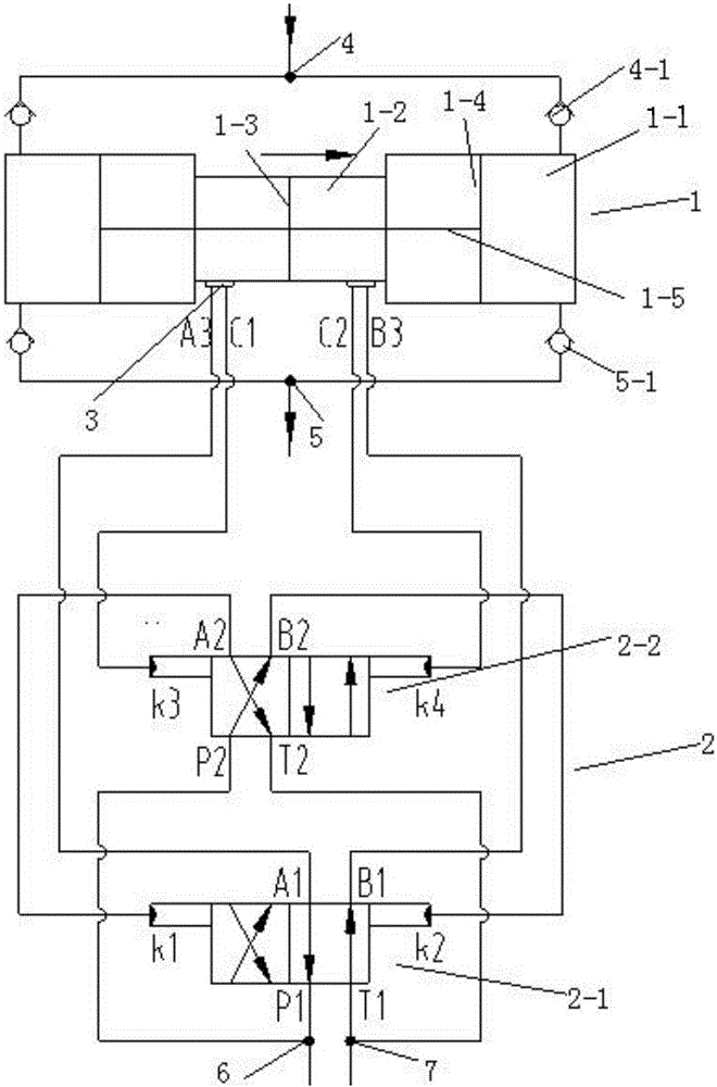
[0023] Please refer to the attached figure 1 , this embodiment includes a water pump body 1 and a hydraulic drive system 2 , the hydraulic drive system 2 communicates with the water pump body 1 , and a signal valve 3 is provided between the hydraulic drive system 2 and the water pump body 1 .

[0024] In this embodiment, the hydraulic drive system 2 includes hydraulically controlled reversing valve one 2-1 and hydraulically controlled reversing valve two 2-2, hydraulically controlled reversing valve one 2-1 and hydraulically controlled reversing valve two 2- 2 are equipped with a working oil port, a driving oil port, an oil inlet and an oil return port, and the working oil ports of the hydraulic control reversing valve 2-1 include A1 port and B1 port, and the hydraulic control reversing valve The working oil port of two 2-2 includes A2 port and B2 port, the driving oil port of said hydraulic control reversing valve one 2-1 includes k1 port and k2 port, and the driving oil port...

Embodiment 2

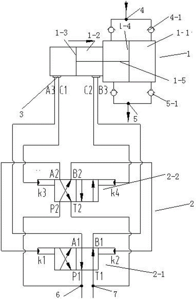
[0041] Please refer to the attached figure 2 , The difference between this embodiment and Embodiment 1 is that the number of the water cylinder 1-2 is one, and the water cylinder 1-2 is arranged on the right side of the oil cylinder 1-1. The rest are basically the same as in Example 1.

[0042] Light weight; the output flow can be adjusted as required; the power direction is consistent with the action direction of the water pump, with low power consumption and high efficiency; strong anti-pollution ability, no unbalanced load of the water pump piston, and increased life; at the end of the stroke of the cylinder 1-1, the hydraulic signal The acquisition methods are diversified and the implementation is simple.

Embodiment 3

[0044] The difference between this embodiment and Embodiment 1 is that the number of the water tank 1-2 is one, and the water tank 1-2 is arranged on the left side of the oil tank 1-1. The rest are basically the same as in Example 1.

[0045] Light weight; the output flow can be adjusted as required; the power direction is consistent with the action direction of the water pump, with low power consumption and high efficiency; strong anti-pollution ability, no unbalanced load of the water pump piston, and increased life; at the end of the stroke of the cylinder 1-1, the hydraulic signal The acquisition methods are diversified and the implementation is simple.


PUM


Abstract

The invention discloses an automatic reversing water pump. The automatic reversing water pump comprises a water pump body and a hydraulic drive system, wherein the hydraulic drive system communicates with the water pump body, and a signal valve is arranged between the hydraulic drive system and the water pump body. According to the automatic reversing water pump disclosed by the invention, a speed reduction device and unnecessary drive mechanisms and signal feedback mechanisms are not arranged, and thus a light weight is achieved; an output flow can be completely adjusted as needed; a power direction is the same as an action direction of the water pump, and thus low power consumption and high efficiency are achieved; the piston-type water pump is high in anti-pollution capacity and capable of easily adapting to poor water quality; straight reciprocating motion is adopted, a piston of the water pump is free from an eccentric load, and the service life is prolonged; and acquisition manners for a hydraulic signal are various at the tail end of a stroke of an oil cylinder, and are simple to realize.

Description

technical field [0001] The invention relates to a water pump, in particular to an automatic reversing water pump. [0002] technical background [0003] A technical implementation route of the current traditional water pump is: using the principle of the crank slider or piston mechanism, the rotation of the crank is converted into the reciprocating linear motion of the slider or piston, in order to meet the appropriate flow requirements and adapt to the movement speed of the piston Requirements, it is often necessary to add a deceleration device between the power and the crank. The existing deceleration device is generally a reduction box, and the weight is relatively large. Another type of plunger water pump is to convert the crank rotation into the reciprocating motion of three plungers. This type of water pump plunger allows a faster reciprocating speed, but has poor anti-pollution ability and is not suitable for water quality containing impurities and particles. . In t...

Claims


Application Information

Patent Timeline
IPC IPC(8): F04B49/00
CPCF04B49/002
Inventor 刘猛朱永峰黎桑李继伟谢俊梁占国
Owner 湖南莫尔顿智能勘探机器人有限公司
Why Eureka
Try Eureka