
Method for monitoring deformation of tunnel pipe-roof

A deformation monitoring and tunnel tube technology, applied in the direction of measuring devices, instruments, and optical devices, can solve the problems of reducing the reliability of inclinometers, reading errors of inclinometers, monitoring interruptions, etc., and achieve simple and practical calculation methods, eliminating The effect of temperature influence and high monitoring accuracy

Active Publication Date: 2017-03-22
QINGDAO TECHNOLOGICAL UNIVERSITY
View PDF6 Cites 21 Cited by
  • Summary
  • Abstract
  • Description
  • Claims
  • Application Information

AI Technical Summary

Problems solved by technology

At present, the inclinometer is generally used to measure the deflection change of the pipe shed deformation monitoring, but when the deformation of the pipe shed is intensified, the curvature of the inclinometer catheter becomes larger, so that the inclinometer cannot pass through the catheter and the monitoring is interrupted; when the inner cavity of the inclinometer catheter enters When there is sediment, it will cause large errors in the readings of the inclinometer, and these problems will reduce the reliability of the inclinometer, resulting in inaccurate judgments on the stability of the pipe shed
The distributed optical fiber sensing technology has the characteristics of good durability, anti-electromagnetic interference, corrosion resistance, etc., and it realizes continuous distributed monitoring, and its biggest advantage is that it can accurately measure the strain, temperature, Various information such as vibration and damage are widely used in the health detection of bridges, dams, high-rise buildings, tunnels and other structures, but the monitoring of the deformation of the tunnel pipe shed has not yet started, and there is no relevant research on the determination method of stability

Method used


Image

  • Method for monitoring deformation of tunnel pipe-roof
  • Method for monitoring deformation of tunnel pipe-roof
  • Method for monitoring deformation of tunnel pipe-roof

Examples


Embodiment Construction

[0053] The present invention will be described in further detail below in conjunction with specific drawings.

[0054] For example Figure 4 The pipe shed shown is monitored, and three steel pipes (the steel pipe to be tested I1.1; the steel pipe to be tested II 1.2; the steel pipe to be tested III 1.3) are selected for monitoring.

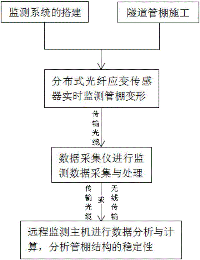
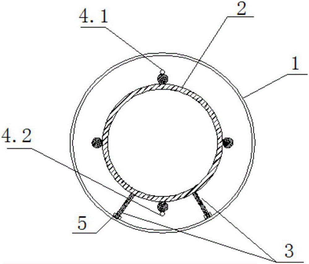
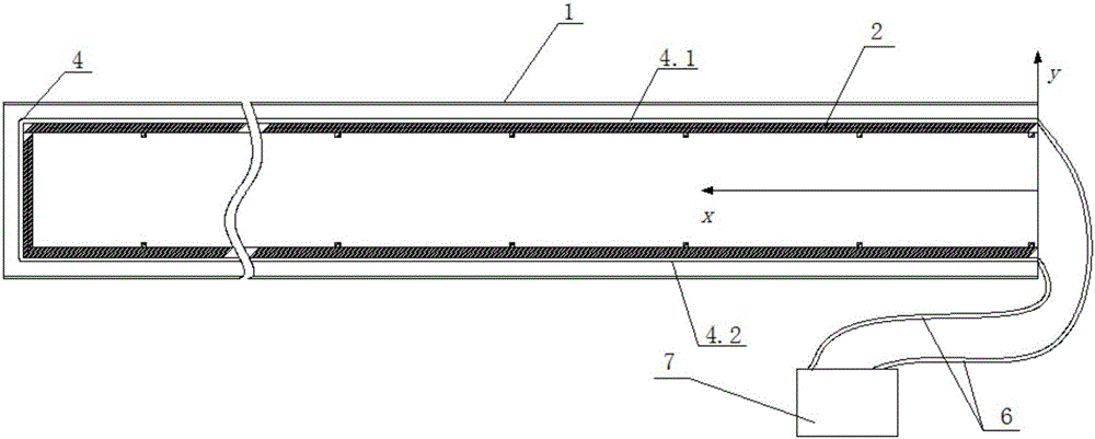
[0055] For each steel pipe to be tested according to the following figure 2 , 3 The arrangement scheme shown is to monitor the deformation of the tunnel pipe shed, including the following steps:

[0056] (1) Layout of the distributed optical fiber sensing circuit 4: After the pipe shed is drilled, the steel pipe 1 to be tested is selected at the tunnel vault and the arch waist position, and then a cylindrical steel cage 2 is prefabricated, and the steel bar The cage 2 is placed horizontally, and the reinforcement support 3 with the push roller 5 is welded below the reinforcement cage 2 . Take the axial cross-section perpendicular to the horiz...


PUM


Abstract

The present invention relates to a method for monitoring the deformation of a tunnel pipe-roof. The method includes the steps of (1) distributed optical fiber strain sensors laying: attaching distributed optical fiber strain sensors to the upper and lower ends of a steel cage, pushing the steel cage into a steel pipe to be measured, and filling cement mortar in the steel pipe to form a joint force bearing deformable body, (2) Data collection: selecting n measurement sections from the steel pipe to be measured with the measurement section distance being delta xi, monitoring vertical deformation of each section under the effect of vertical loads on a real-time basis by a data acquisition instrument and transmitting the vertical deformation to a monitoring host, and (3) deformation calculation and stability judgment: the monitoring host using Brillouin mediation technology and material mechanics theory to calculate the longitudinal strain difference of each cross section and obtain the deflection wi of the steel pipe to be measured. The monitoring method is quick and easy, the monitoring data is high in precision, and temperature is self-compensating. Monitoring equipment is connected with a data acquisition instrument, through which data is transmitted to a monitoring host, to realize real-time on-line monitoring of the pipe-roof deformation.

Description

technical field [0001] The invention relates to a method for monitoring the deformation of pipe shed support under tunnel construction, in particular to a method for measuring the bending moment, deflection and stress change of the tunnel pipe shed. Background technique [0002] As the process of urbanization is accelerating, the traffic volume in many urban areas has accelerated, and the pressure on urban traffic has also increased. Compared with the increasingly saturated above-ground space, the development and utilization of underground space has become an effective way to solve the problem of traffic congestion, and the construction of urban tunnels has also become an important means of underground space development. The shallow buried underground excavation method has little impact on the surrounding environment, is economical and practical, and is widely used in tunnel construction. Due to the poor conditions of the surrounding rock during the construction process of ...

Claims


Application Information

Patent Timeline
Patent Type & Authority Applications(China)
IPC IPC(8): G01B11/16
CPCG01B11/16
Inventor 袁长丰陈杨李聪明
Owner QINGDAO TECHNOLOGICAL UNIVERSITY
Learn More