Compensation Topology for Wireless Power Transfer Systems

A technology of wireless power transmission and compensation topology, which is applied in the direction of control/regulation systems, electrical components, circuit devices, etc., can solve the problems of high system cost, large number of compensation components, and low power density, so as to enhance flexibility and reduce system cost. The effect of cost and power density improvement

Inactive Publication Date: 2018-12-11
HARBIN INST OF TECH
View PDF3 Cites 1 Cited by
  • Summary
  • Abstract
  • Description
  • Claims
  • Application Information

AI Technical Summary

Problems solved by technology

[0006] The purpose of the present invention is to provide a compensation topology of the wireless power transmission system in order to solve the problems of a large number of compensation devices, high system cost and low power density in the existing wireless power transmission system

Method used


Image

  • Compensation Topology for Wireless Power Transfer Systems
  • Compensation Topology for Wireless Power Transfer Systems
  • Compensation Topology for Wireless Power Transfer Systems

Examples


specific Embodiment approach 1

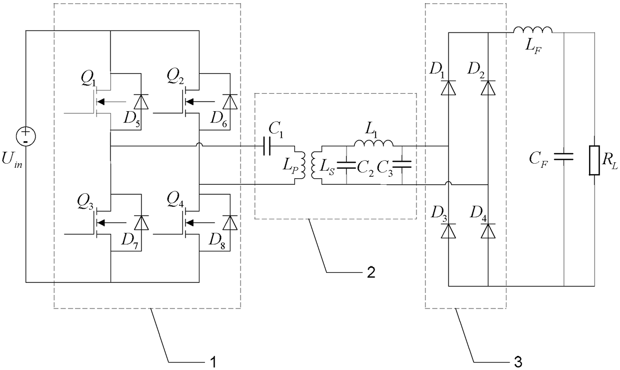
[0019] Specific embodiment one: the following combination figure 1 This embodiment will be described. The wireless power transmission system compensation topology in this embodiment includes a DC input voltage source U. in , full-bridge inverter 1, S / CLC compensation topology 2, full-wave rectifier 3, filter inductor L F , filter capacitor C F and load resistance R L ;

[0020] One DC input terminal of the full-bridge inverter 1 is connected to the DC input voltage source U in The positive pole of the full-bridge inverter 1 is connected to the other DC input terminal of the DC input voltage source U in the negative pole;

[0021] S / CLC compensation topology 2 includes primary series compensation capacitor C 1 , Loosely coupled transformer, secondary side parallel compensation capacitor C 2 , Secondary series compensation inductance L 1 and the phase-shift capacitor C 3 ;Primary series compensation capacitor C 1 One end of the inverter is connected to an AC output end...

specific Embodiment approach 2

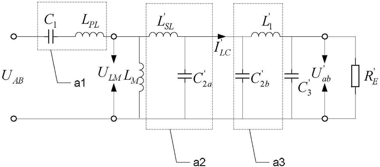
[0024] Embodiment 2: This embodiment further describes Embodiment 1. The parameter selection of S / CLC compensation topology 2 includes a series compensation capacitor C 1 , the secondary side parallel compensation capacitor C 2 , Secondary series compensation inductance L 1 and the phase-shift capacitor C 3 the value of;

[0025] The parameter selection is based on the following:

[0026] Step 1. Determine the working angular frequency ω of the system according to the given parameters S , Loosely coupled transformer primary side self-inductance L P , the secondary side self-inductance L S and the coupling coefficient k; the given parameters include the system output power P RL , size, transmission distance and quality;

[0027] Step 2. When the phase shift angle of the full-bridge inverter 1 is 0°, obtain the secondary side series compensation inductance L according to formula (1). 1 The value of:

[0028]

[0029] In the formula, R L is the load resistance, U in...

specific Embodiment approach 3

[0036] Embodiment 3: This embodiment further describes Embodiment 1, C 3 It is a phase-shifting capacitor used to adjust the input impedance angle.


PUM


Abstract

A compensation topology structure of a wireless power transmission system relates to a compensation topology structure of a wireless power transmission system. The invention solves the problems of a large number of compensation components, higher system cost and lower power density of the existing wireless power transmission system compensation topology structure. The S / CLC compensation topology includes primary series compensation capacitors, loosely coupled transformers, secondary parallel compensation capacitors, secondary series compensation inductors and phase-shifting capacitors; the primary series compensation capacitors are connected to the full-bridge inverter, and the primary series compensation capacitors are connected The self-inductance of the primary side of the loosely coupled transformer, the self-inductance of the primary side of the loosely coupled transformer is connected to the full-bridge inverter, the self-inductance of the secondary side of the loosely coupled transformer is connected to the parallel compensation capacitor of the secondary side and the series compensation inductance of the secondary side, and the self-inductance of the secondary side of the loosely coupled transformer is connected. The secondary side is connected in parallel with the compensating capacitor, the phase-shifting capacitor and the full-wave rectifier, and the secondary side is connected in series with the compensating capacitor and the phase-shifting capacitor and the full-wave rectifier. The present invention is used for wireless power transfer.

Description

technical field [0001] The invention relates to a compensation topology of a wireless power transmission system. Background technique [0002] Wireless power transmission has at least four requirements for compensation topology: ① It can realize the input zero phase angle (ZeroPhase Angle, ZPA), and the zero voltage switching (Zero Voltage Switching, ZVS) is easy to debug; ② Compensation topology end output voltage / current and The load is irrelevant; ③ The output voltage / current of the system is not limited by the loosely coupled transformer; ④ The number of compensation components is small, and the system power density and efficiency are high. The system output voltage / current is not limited by the loosely coupled transformer, which means that for a given load, without changing the input voltage and operating frequency of the wireless power transmission system, and without replacing the loosely coupled transformer, only by adjusting the parameters of the system compensation...

Claims


Application Information

Patent Timeline
Patent Type & Authority Patents(China)
IPC IPC(8): H02M3/335H02J50/12
CPCH02M3/335H02M1/0058Y02B70/10
Inventor 刘晓胜姚友素王懿杰张潇锐刘梦雨徐殿国
Owner HARBIN INST OF TECH
Why Eureka
Try Eureka