Device and method for cutting optical fiber through laser

A technology of laser cutting and optical fiber, which is applied in laser welding equipment, welding equipment, metal processing equipment, etc., can solve the problems of not being able to obtain light spots, cost consumption of large sandpaper, troublesome mass production, etc., and reduce the quality requirements of light source beams and equipment Complexity, effect of improving motion precision

A technology of laser cutting and optical fiber, which is applied in laser welding equipment, welding equipment, metal processing equipment, etc., can solve the problems of not being able to obtain light spots, cost consumption of large sandpaper, troublesome mass production, etc., and reduce the quality requirements of light source beams and equipment Complexity, effect of improving motion precision

CN106563881AInactive Publication Date: 2017-04-19WUHAN LINGYUN PHOTOELECTRONICS SYST

Image

  • Device and method for cutting optical fiber through laser
  • Device and method for cutting optical fiber through laser
  • Device and method for cutting optical fiber through laser

Examples


Embodiment Construction

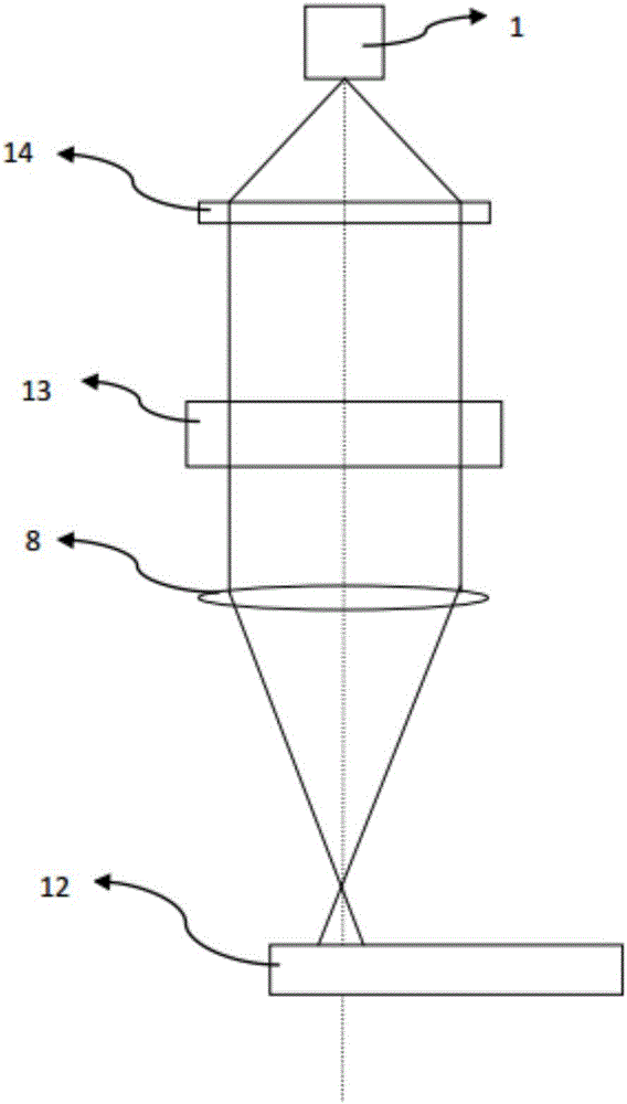
[0027] like figure 1 As shown, it is a schematic diagram of an existing laser cutting optical fiber device, which includes a working laser source 1, a collimating mirror 14, a beam rectangle changing device 13, a focusing mirror 8, and an optical fiber 12 to be processed.

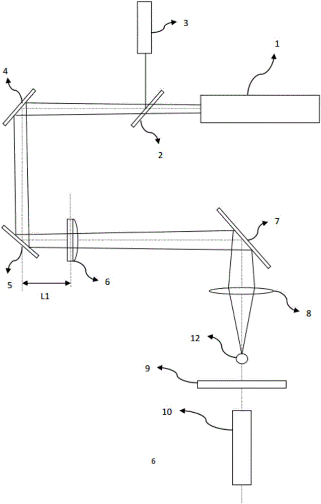
[0028] like figure 2 Shown is a schematic diagram of a laser cutting optical fiber device of the present invention, which includes: a processing laser source 1, a beam combining mirror 2, an indicating laser source 3, a first reflecting mirror 4, a second reflecting mirror 5, a shaping cylindrical mirror 6, The third reflecting mirror 7 , focusing mirror 8 , mechanical gate 9 , video camera 10 , air nozzle 11 , linear adjustment platform 15 , adjustment frame 16 and rotation adjustment frame 17 . Among them, the laser light source 1 used in this embodiment is used to generate a high-energy pulsed laser beam, with a wavelength of 10.6uM, a beam quality of 1.5, an average power of 100W, a peak power of 250W...


PUM

PropertyMeasurementUnit
diameteraaaaaaaaaa

Abstract

The invention relates to the technical field of laser cutting, in particular to a device and method for cutting an optical fiber through a laser. The device comprises a working laser source, a first reflecting mirror, a second reflecting mirror, a third reflecting mirror and a focusing mirror. A 45-degree included angle is formed between the optical axis of the laser output through the working laser source and the first reflecting mirror. The first reflecting mirror is perpendicular to the second reflecting mirror, and the reflecting surface of the first reflecting mirror and the reflecting surface of the second reflecting mirror correspond to each other. The third reflecting mirror is located at the backward stage of the second reflecting mirror. After being subjected to transition beam expanding through the first reflecting mirror and the second reflecting mirror, the laser output through the working laser source is reflected through the third reflecting mirror and focused to the to-be-processed optical fiber through the focusing mirror. Laser beam shaping and precise processing angle control are achieved through the combination of the first reflecting mirror, the second reflecting mirror, the third reflecting mirror, a shaping cylindrical mirror and the focusing mirror, and the end surface shape of the optical fiber is precisely controlled by adjusting the included angle b of the third reflecting mirror as well as the distance L2 between the focusing mirror and the third reflecting mirror, so that the end surface notch angle of the optical fiber is adjustable.

Description

technical field [0001] The invention relates to the technical field of laser cutting, in particular to a device and method for laser cutting optical fibers. Background technique [0002] Optical fiber cutting and polishing is a critical process in the manufacture of optical fiber connectors. When optical fiber is connected, the fiber end face needs to be processed to obtain a clean and flat surface, and the surface sometimes needs to be perpendicular to the fiber axis or have a specific angle to the fiber axis. If high-quality optical fiber surface is required, polishing is usually performed after mechanical cleavage. In the field of optical fiber jumper production, the pigtail grinding process with ferrule is very mature. However, bare optical fibers must be used directly in some special fields, such as MTP / MPO fiber optic connectors. The traditional mechanical cutting and polishing methods have high processing costs and low yields. [0003] Mechanical cutting is a tradi...

Claims


Application Information

Patent Timeline
19 Apr 2017
Publication
CN106563881A
IPC
B23K26/38; B23K26/70
CPC
B23K26/38; B23K26/702
Inventors
林卿