Multimode and multi-based unmanned aerial vehicle with tailed flying wing configuration

A technology of unmanned aerial vehicles and flying wings, applied in the field of flying wing unmanned aerial vehicles, can solve the problems of high research and development costs and difficulty in research and development, and achieve the effect of excellent aerodynamic characteristics, high effective loading factor, and high-efficiency integrated layout

Inactive Publication Date: 2017-04-26
CHINA ELECTRONIC TECH GRP CORP NO 38 RES INST
View PDF6 Cites 18 Cited by
  • Summary
  • Abstract
  • Description
  • Claims
  • Application Information

AI Technical Summary

Problems solved by technology

[0006] As mentioned above, there are only two types of aircraft with vertical take-off and landing functions and high-speed cruising capabilities that have been put into practical use at present: vertical take-off and landing aircraft that use jet engine thrust steering and tilt-rotor / propeller powered vertical take-off and landing aircraft. Its research and development costs are high and research and development is extremely difficult

Method used


Image

  • Multimode and multi-based unmanned aerial vehicle with tailed flying wing configuration
  • Multimode and multi-based unmanned aerial vehicle with tailed flying wing configuration
  • Multimode and multi-based unmanned aerial vehicle with tailed flying wing configuration

Examples


Embodiment 1

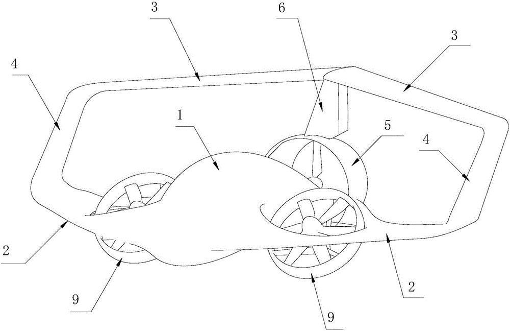
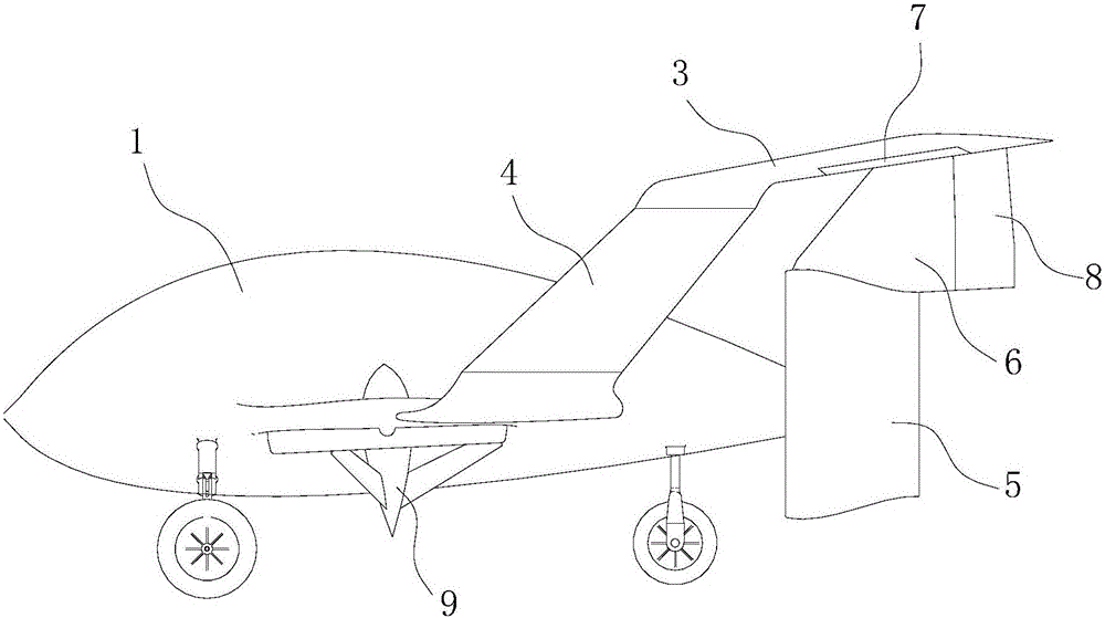
[0038] Such as figure 1 , 2 , Shown in 3, a kind of multi-mode multi-base unmanned aerial vehicle with tail flying wing layout, this aircraft comprises: the lifting body type fuselage 1 that longitudinal section is airfoil plane shape, the wing-body fusion type that is arranged on fuselage 1 both sides Main wing 2, upper wing 3, end wing 4, ducted propeller propulsion device 5 and vertical tail 6 arranged at the fuselage 1 tail. The main wing 2 arranged on both sides of the fuselage 1 is provided with an end wing 4 at the tip of the wing, and the upper parts of the two end wings 4 pass through the upper wing 3 arranged above the fuselage 1 and the rear wing arranged at the tail of the fuselage 1 respectively. The vertical tail 6 is connected, and the lower end of the vertical tail 6 is fixedly connected with the duct structure of the ducted propeller propulsion device 5 arranged at the fuselage 1 tail.

[0039] The unmanned aerial vehicle provided by the present invention ad...

Embodiment 2

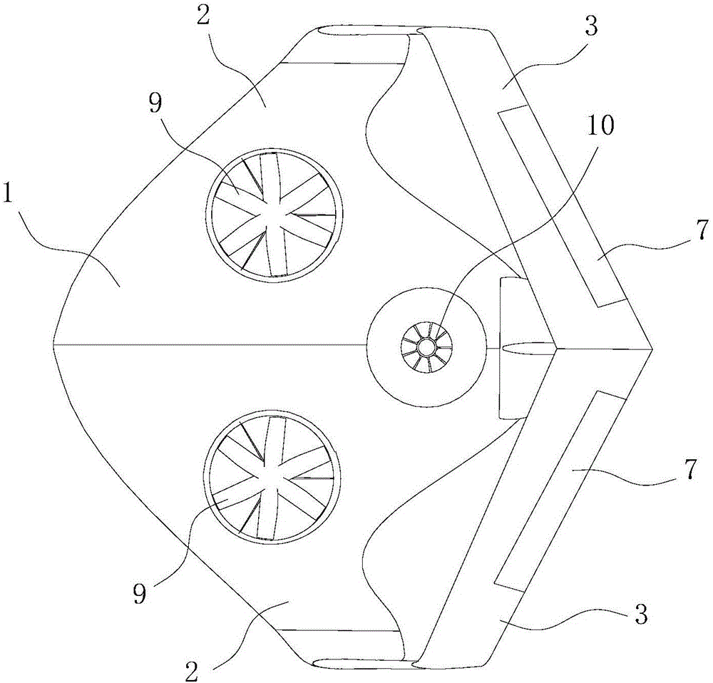
[0041] According to an embodiment of the present invention, the multi-mode and multi-base unmanned aerial vehicle with tail flying wing layout provides a high-efficiency integrated energy power system design scheme, such as image 3 shown. Its features include:

[0042] The unmanned aerial vehicle adopts a layout form in which ducted fans 9 are arranged on both sides of the front of the fuselage 1 and before the center of gravity, so as to generate direct lifting force during the vertical take-off and landing phase. Such as Figure 4As shown, the ducted fans 9 on both sides of the fuselage 1 rotate in opposite directions, and are fixedly connected to both ends of the horizontal shaft 13 installed in the fuselage 1 . The ducted fan 9 is driven by two DC motors 15 turning in opposite directions and generates pulling force. The servo motor 12 installed in the fuselage 1 drives the worm gear 11 and meshes with the worm gear 14 on the horizontal shaft 13 . Both the servo motor ...

Embodiment 3

[0045] According to an embodiment of the present invention, the multi-mode multi-base unmanned aerial vehicle with tail flying wing layout, the system state under the vertical take-off and landing mode is as follows Figure 7 shown. Under the vertical take-off and landing working mode, the heavy oil piston type power unit 25 at the rear of the fuselage 1 remains in a "quiet" state. The ducted fan 9 on both sides of the fuselage 1 rotates to such as Figure 4 The shown vertical position rotates at a high speed and produces upward lifting force; the clutch 20 at the output end of the turbojet main shaft 19 is released, and the high-temperature and high-pressure gas expands in the exhaust nozzle 18 and produces a vertical upward thrust, that is, the lifting force , and the ducted fan 9 jointly generate enough lift to realize vertical take-off and landing under direct force control in the vertical direction. In addition, the jet thrust produced by the turbojet engine 10 can also...


PUM


Abstract

The invention relates to the technical field of unmanned aerial vehicles, and particularly relates to an unmanned aerial vehicle with a tailed flying wing configuration, which has a plurality of working modes such as vertical take-off and landing / short-distance take-off and landing / conventional take-off and landing / low-speed forward flight / high-speed forward flight and the like and can realize coast-based / vessel-based multi-based configuration. The unmanned aerial vehicle comprises a lifting body type vehicle body of which the longitudinal section is of an airfoil shape, and main airfoils, upper airfoils and end airfoils which are arranged at both sides of the vehicle body and form smooth integration with the vehicle body, and a duct propeller propulsion device and a vertical fin which are arranged at the tail of the vehicle body, wherein the lower end of the vertical fin is fixedly connected with a duct structure of the duct propeller propulsion device arranged at the tail of the vehicle body. According to the invention, the tailed flying wing configuration integrated with jointed wings is adopted, so that the unmanned aerial vehicle has various advantages such as excellent aerodynamic characteristics and high effective load factor of the conventional flying wing configuration, and also effectively overcomes the inherent defects of the conventional flying wing configuration in aspects of stability and operability.

Description

technical field [0001] The invention relates to the technical field of unmanned aerial vehicles, belongs to the technical field of design of fixed-wing aircraft in aviation aircraft, and specifically relates to a multi-function aircraft with vertical take-off and landing / short-distance take-off and landing / conventional take-off and landing / low-speed forward flight / high-speed forward flight, etc. Modal, it can realize shore-based / ship-based multi-base deployment, and integrates a flying-wing unmanned aerial vehicle in the form of aerodynamic layout of joint wings. Background technique [0002] At present, the aircraft with VTOL / STOL functions and capable of shore-based / ship-based multi-base deployment can be mainly divided into helicopters, VTOL aircraft using jet engine thrust steering, tilt-rotor / propeller powered VTOL aircraft, etc. Several types of landing aircraft. [0003] Among them, helicopters have been widely used in military and civilian fields due to their excell...

Claims


Application Information

Patent Timeline
Patent Type & Authority Applications(China)
IPC IPC(8): B64D27/16B64D27/04B64C11/00B64C5/06B64C5/08B64C9/00H02J7/00
CPCH02J7/00B64C5/06B64C5/08B64C9/00B64C11/00B64D27/04B64D27/16B64U50/12B64U50/11B64U10/25B64U50/14
Inventor 李翔吴晴赵昌霞谢奎方坦荣海春
Owner CHINA ELECTRONIC TECH GRP CORP NO 38 RES INST
Why Eureka
Try Eureka