
An anaerobic built-in rusty iron filings reactor for efficient removal of ammonia nitrogen and its process for treating ammonia nitrogen wastewater

A reactor and ammonia removal technology, applied in anaerobic digestion treatment, electrochemical biological combination treatment, water/sewage treatment, etc., can solve the problems of low removal efficiency, long time-consuming anaerobic ammonia nitrogen removal, etc., to reduce the cost and cost , processing capacity and stability enhancement, and the effect of promoting anaerobic removal

Active Publication Date: 2020-06-16
DALIAN UNIV OF TECH
View PDF1 Cites 0 Cited by
  • Summary
  • Abstract
  • Description
  • Claims
  • Application Information

AI Technical Summary

Problems solved by technology

[0005] In order to overcome the defects of long time-consuming anaerobic ammonia nitrogen removal and low removal efficiency in the prior art, the present invention proposes the following technical proposal: an anaerobic built-in rusted iron filings reactor for efficiently removing ammonia nitrogen, which is characterized in that: the box body and the There is a circulating water chamber between the inner chambers of the reactor, and the fixed electrode anode and electrode cathode under the inner chamber of the reactor are respectively connected to the positive and negative poles of the power supply through wires.

Method used


Image

  • An anaerobic built-in rusty iron filings reactor for efficient removal of ammonia nitrogen and its process for treating ammonia nitrogen wastewater
  • An anaerobic built-in rusty iron filings reactor for efficient removal of ammonia nitrogen and its process for treating ammonia nitrogen wastewater

Examples


Embodiment Construction

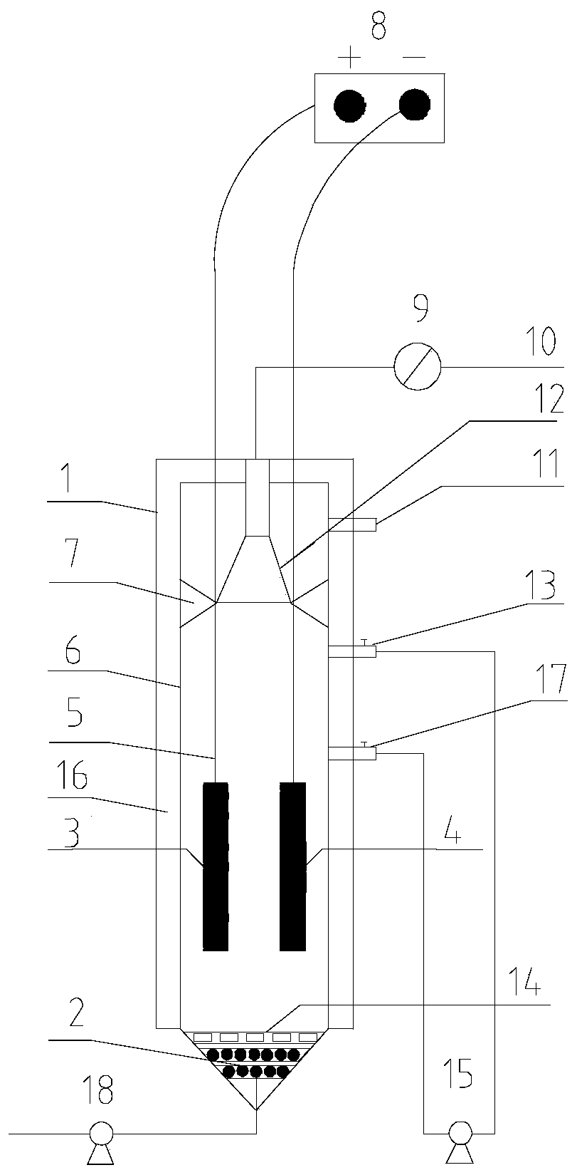
[0022] The present invention will be further described below in conjunction with the accompanying drawings and embodiments. attached figure 1 It is a structural schematic diagram of an anaerobic built-in rusty iron chip reactor for efficiently removing ammonia nitrogen in the present invention. It includes a box body 1, an anaerobic sludge layer 2, rusty iron filings 14, and a reactor inner chamber 6. A circulating water cavity 16 is provided between the box body 1 and the reactor inner cavity 6 . The electrode anode 3 (carbon brush) and electrode cathode 4 (carbon rod) fixed below the reactor inner chamber 6 are respectively connected to the positive and negative poles of the power supply 8 through wires 5 . A baffle 7 is arranged above the inner cavity 6 of the reactor and a three-phase separator 12 is fixed on the upper end thereof, and the upper end of the three-phase separator 12 communicates with an outlet pipe 10 through a gas flow meter 9 . The inner cavity of the ...


PUM


Abstract

The invention provides an anaerobic built-in rusted iron scrap reactor for efficiently removing ammonia nitrogen, and a process for treating ammonia nitrogen wastewater. The process is especially suitable to treat anaerobic high-concentration ammonia nitrogen wastewater. The process comprises the following steps of filling a sludge layer of the anaerobic built-in rusted iron scrap reactor with anaerobic sludge acclimated through ammonia nitrogen wastewater; adding pretreated rusted iron scraps to the anaerobic built-in rusted iron scrap reactor to be fully mixed with the anaerobic sludge; putting a pair of a positive electrode and a negative electrode into the anaerobic built-in rusted iron scrap reactor at the same time; connecting the two electrodes with the positive and negative electrodes of a power supply through lead wires; and realizing the treatment of the anaerobic enhanced high ammonia nitrogen wastewater through the dissimilatory iron effect of the sludge in the rusted iron scrap enhanced anaerobic reactor and anodic oxidation, coupled with cathode denitrification, of ammonia nitrogen. The process overcomes the technical defects of low anaerobic ammonia nitrogen removal efficiency and relatively long consumed time, and is a new anaerobic ammonia nitrogen wastewater treatment process which is efficient, low in price and low in consumption.

Description

technical field [0001] The invention relates to a wastewater treatment process in the field of environmental protection. Background technique [0002] Excessive discharge of ammonia nitrogen leads to increasingly serious eutrophication of water bodies, and its oxidation products of nitrate and nitrite will seriously affect the health of aquatic organisms and humans. Therefore, efficient treatment of ammonia nitrogen in wastewater has become a major issue facing the environment today. At present, the methods of ammonia nitrogen removal mainly include biological nitrification-denitrification, break point chlorination, gas stripping and ion exchange. Although the traditional stripping method has stable ammonia removal effect and simple operation, its disadvantages are that it is greatly affected by the ambient temperature, the stripping efficiency is limited, the operating cost is high, and the consumption of chemicals is large when adjusting the pH, so this technology is main...

Claims


Application Information

Patent Timeline
Patent Type & Authority Patents(China)
IPC IPC(8): C02F3/28C02F1/461
CPCC02F1/4676C02F3/005C02F3/28
Inventor 张耀斌朱婷婷
Owner DALIAN UNIV OF TECH
Learn More