
Adjustable phase change heat storage floor based on heat storage heating pipes

A technology of phase change heat storage and heating pipes, which is applied in the direction of heat storage equipment, heat exchanger type, space heating and ventilation details, etc., can solve the problems of inability to feedback and adjust the heat supply of the floor system, low utilization rate of phase change materials, Problems such as poor heat exchange effect can be achieved to alleviate the peak power shortage, increase latent heat storage, and increase thermal inertia

Inactive Publication Date: 2017-04-26
TIANJIN UNIV
View PDF10 Cites 5 Cited by
  • Summary
  • Abstract
  • Description
  • Claims
  • Application Information

AI Technical Summary

Problems solved by technology

There have been a lot of researches on the phase change heat storage floor. There are many ways to combine the floor radiant heating pipe and the phase change material. The outer wall of the floor radiant heating pipe and the phase change material are in indirect contact, and the heat transfer effect is not good. The use of phase change material The heat supply rate of the floor system is low, and the heat supply of the floor system cannot be adjusted according to the heat load. It is easy to cause a large amount of heat supply at the beginning and end of the heating period, and the room temperature is too high. When the heat load is large, the room temperature may not be guaranteed.

Method used


Image

  • Adjustable phase change heat storage floor based on heat storage heating pipes
  • Adjustable phase change heat storage floor based on heat storage heating pipes
  • Adjustable phase change heat storage floor based on heat storage heating pipes

Examples


Embodiment 1

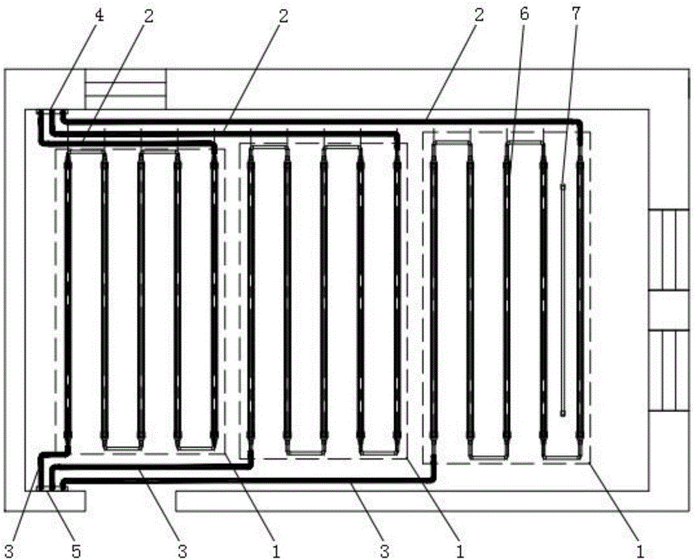
[0036] In this embodiment, the heat storage floor of the present invention adopts three sets of heating pipe modules 1, and its working process is as follows:

[0037] A temperature sensor is set outdoors to sense the outdoor temperature. During the heating period, when the outdoor temperature is higher than 0°C, only open the valves of one set of heating pipe module 1, and close the valves of the other two sets of heating pipe module 1; when the outdoor temperature is -10~0°C, open the two sets of heating For the valves of pipe module 1, close the valves of the third group of heating pipe module 1; when the outdoor temperature is below -10°C, open the valves of three groups of heating pipe module 1. Turn on the heat source and circulation pump to heat the room and store energy. After the energy storage is completed, the rest of the time depends on the energy stored in the floor to maintain the indoor temperature.


PUM


Abstract

The invention discloses an adjustable phase change heat storage floor based on heat storage heating pipes. The adjustable phase change heat storage floor comprises a structural layer, a damp-roof layer, a thermal insulating layer, a packing layer and a decoration surface layer. A plurality of heating pipe modules are laid in the packing layer, connected in parallel in an equal pipe road mode, and arranged between a water distributing device and a water collecting device located on the two sides of a room. A water inlet of each heating pipe module is connected to the water distributing device through a water supply pipe of the module. A water outlet of each heating pipe module is connected to the water collecting device through a water return pipe of the module. Each heating pipe module is a loop composed of the multiple heat storage heating pipes connected in series. The packing layer is further internally provided with heat storage bars. By adoption of the adjustable phase change heat storage floor, efficient and diversified utilization of solar energy in building heating in winter can be achieved, and the problem that coal-fired heating is adopted in rural areas in northern China and the environment is polluted is relieved; and meanwhile, the problem of peak power shortage can be solved, peak-load shifting is achieved, and development of coal-to-electricity projects is facilitated.

Description

technical field [0001] The invention relates to the technical field of building energy saving and new energy utilization, in particular to an adjustable phase-change heat storage floor based on heat storage heating pipes. Background technique [0002] At present, the main energy sources in the world are coal, oil and natural gas. Oil and gas resources will be exhausted by 2050. With the development of the economy, the world's primary energy consumption continues to increase, and coal is the fastest growing fossil fuel in the world. It is well known that the use of fossil fuels results in a large amount of carbon emissions and disrupts the ecological balance. China's energy supply mainly depends on coal, which accounts for 76% of all energy consumption. At present, my country's energy utilization technology is backward and inefficient, and a large amount of coal is consumed in direct combustion, which causes air pollution and directly endangers people's health. It is imper...

Claims


Application Information

Patent Timeline
Patent Type & Authority Applications(China)
IPC IPC(8): F24D13/02F24D19/10F28D20/02
CPCF24D13/024F24D19/1096F28D20/021Y02B30/00Y02E60/14
Inventor 吕石磊唐晓磊张力
Owner TIANJIN UNIV
Learn More