
Integrated soaking radiator

A radiator and soaking plate technology, applied in indirect heat exchangers, lighting and heating equipment, cooling/ventilation/heating renovation, etc., can solve the problems of inability to guarantee the effect of flat heat pipes, high processing risks, and many solder joints, etc. Achieve the effect of lowering temperature, simple structure and prolonging service life

Inactive Publication Date: 2017-04-26
南京艾科美热能科技有限公司
View PDF7 Cites 0 Cited by
  • Summary
  • Abstract
  • Description
  • Claims
  • Application Information

AI Technical Summary

Problems solved by technology

With this structure, there are many solder joints, the processing risk is high, and it is easy to leak, so the effect of the flat heat pipe cannot be guaranteed.

Method used


Image

  • Integrated soaking radiator
  • Integrated soaking radiator
  • Integrated soaking radiator

Examples


Embodiment 1

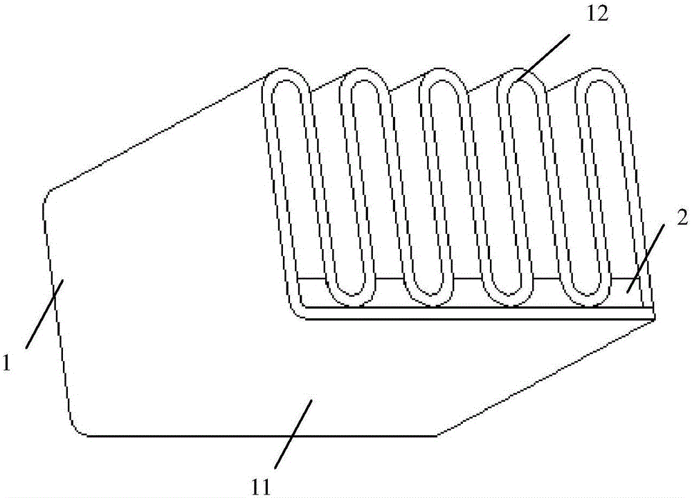
[0040] combine figure 1 , an integrated soaking radiator, which is formed by bending a soaking plate 1, one side of which is used as a bottom plate 11, and the other side is bent into a serpentine structure, serving as the main fin 12 of the radiator; the main fin 12 includes a flat plate and an arc-shaped plate connected at intervals, the flat plate is perpendicular to the bottom plate 11, and the arc-shaped plate at the bottom is welded to the bottom plate 11 through the connector 2;

[0041] The vapor chamber includes an upper cover plate and a lower cover plate. Channels 4 are respectively processed on the opposite sides of the upper cover plate and the lower cover plate. The channel structures of the upper cover plate and the lower cover plate are the same, and the channels are one or more Parallel serpentine channels, the connection surface of the upper cover plate and the lower cover plate are welded, and the channels opposite the upper cover plate and the lower cover p...

Embodiment 2

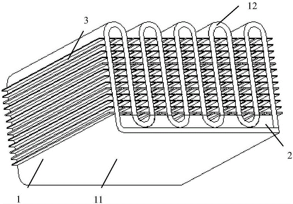
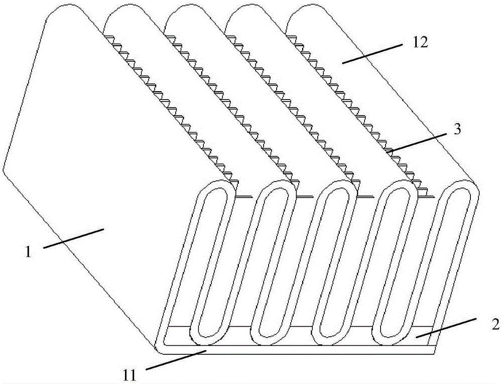
[0045] Such as figure 2 with image 3 As shown, the difference between this embodiment and Embodiment 1 is that several straight ribs 3 are welded on the surface of the main fin 12, and the straight ribs 3 are parallel to the bottom plate.

Embodiment 3

[0047] combine figure 1 , an integrated soaking radiator, which is formed by bending a soaking plate 1, one side of which is used as a bottom plate 11, and the other side is bent into a serpentine structure, serving as the main fin 12 of the radiator; the main fin 12 includes a flat plate and an arc-shaped plate connected at intervals, the flat plate is perpendicular to the bottom plate 11, and the arc-shaped plate at the bottom is welded to the bottom plate 11 through the connector 2;

[0048]The vapor chamber is a hollow structure. The inner wall of the cavity is provided with metal mesh or sintered metal powder to form a capillary structure. The internal cavity is evacuated and filled with working fluid. The working fluid is heated and evaporated in the cavity and refluxed and condensed through the capillary structure to realize heat transfer.


PUM


Abstract

The invention discloses an integrated soaking radiator. The integrated soaking radiator is formed by bending a soaking plate; one side of the soaking plate is used as a bottom plate, and the other side of the soaking plate is bent to be of a snake-shaped structure serving as a main fin of the radiator; the main fin comprises flat plates and arc-shaped plates which are connected in a spacing manner; the flat plates are perpendicular to the bottom plate; the arc-shaped plates located at the bottom are welded with the bottom plate through connection pieces; a cavity is formed in the soaking plate; the cavity is internally vacuumized and filled with a working medium; and the working medium is evaporatively condensed in the cavity to realize heat transmission. The integrated soaking radiator has the advantages of simple structure, high heat transfer efficiency, simple manufacturing process, wide application range and the like, and can effectively and quickly reduce the temperature of an electronic device and prolong the service life of the electronic device.

Description

technical field [0001] The invention belongs to the field of enhanced heat transfer and cooling of electronic components, and in particular relates to an integrated heat-spreading radiator. Background technique [0002] Radiators are widely used in the heat dissipation system of high heat flux devices such as electronic equipment, and play an important role in ensuring the reliability and stability of devices. However, the base plate of ordinary radiators is copper or aluminum, and the thermal conductivity is average; at the same time, the height of the heat sink is also limited. Certain restrictions, when the height of the heat sink is too high, the end heat sink basically does not work. [0003] Some products process the bottom plate of the radiator into a vapor chamber to improve the thermal conductivity of the bottom plate. The heat sink is generally connected to the vapor chamber by welding. This structure has a large contact heat between the heat sink and the heat sink...

Claims


Application Information

Patent Timeline
Patent Type & Authority Applications(China)
IPC IPC(8): F28D15/02H05K7/20
CPCF28D15/0233H05K7/20336
Inventor 徐德好余涛杨佳
Owner 南京艾科美热能科技有限公司
Learn More