Rub-impact sound emission fault position identification method based on near field sound source focusing positioning

A technology of fault location and identification method, which is applied in the direction of measuring devices, testing of mechanical components, testing of machine/structural components, etc., can solve the problem that information is not fully utilized, the identification of rubbing fault sources fails to play its due role, Acoustic emission source location can not get satisfactory results and other problems

Inactive Publication Date: 2017-04-26
SOUTHEAST UNIV
View PDF4 Cites 14 Cited by
  • Summary
  • Abstract
  • Description
  • Claims
  • Application Information

AI Technical Summary

Problems solved by technology

Forward-backward spatial smoothing method (N-FSS), which sacrifices effective array aperture to achieve decorrelation of signal sources; improved near-field MUSIC algorithm (N-IMUSIC), corrects the signal covariance matrix output by the array, so as to effectively estimate the acoustic emission However, such methods cannot obtain satisfactory results for acoustic emission source localization. The main reason is that the improved MUSIC algorithm is suitable for narrowband sound source localization estimation, while the information of wideband acoustic emission signals is not fully utilized.
[0007] Therefore, the identification of rubbing fault sources based on AE technology has not yet played its due role

Method used


Image

  • Rub-impact sound emission fault position identification method based on near field sound source focusing positioning
  • Rub-impact sound emission fault position identification method based on near field sound source focusing positioning
  • Rub-impact sound emission fault position identification method based on near field sound source focusing positioning

Examples


Embodiment Construction

[0048] The present invention will be further described below in conjunction with embodiment and accompanying drawing.

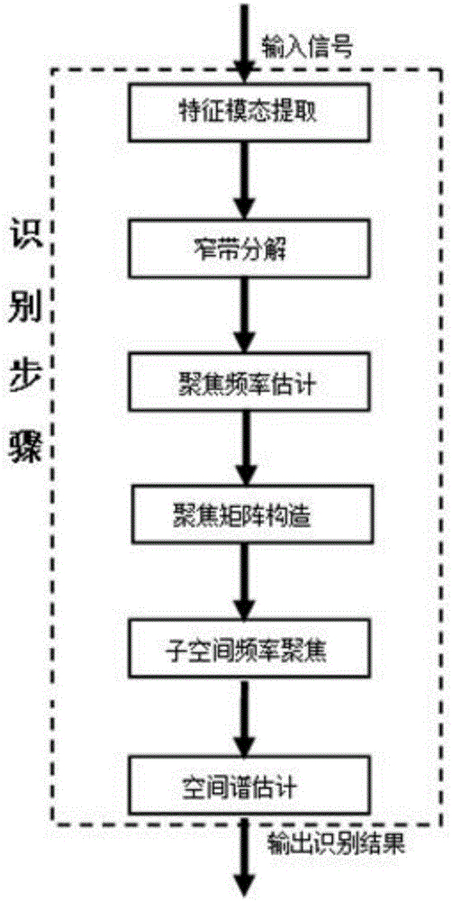
[0049] figure 1 It is a flow chart of multi-coherent acoustic emission source localization based on subspace focusing. The technical solution of the present invention will be further elaborated below in conjunction with the drawings and embodiments.

[0050] 1. Acquisition of rotor friction acoustic emission signal

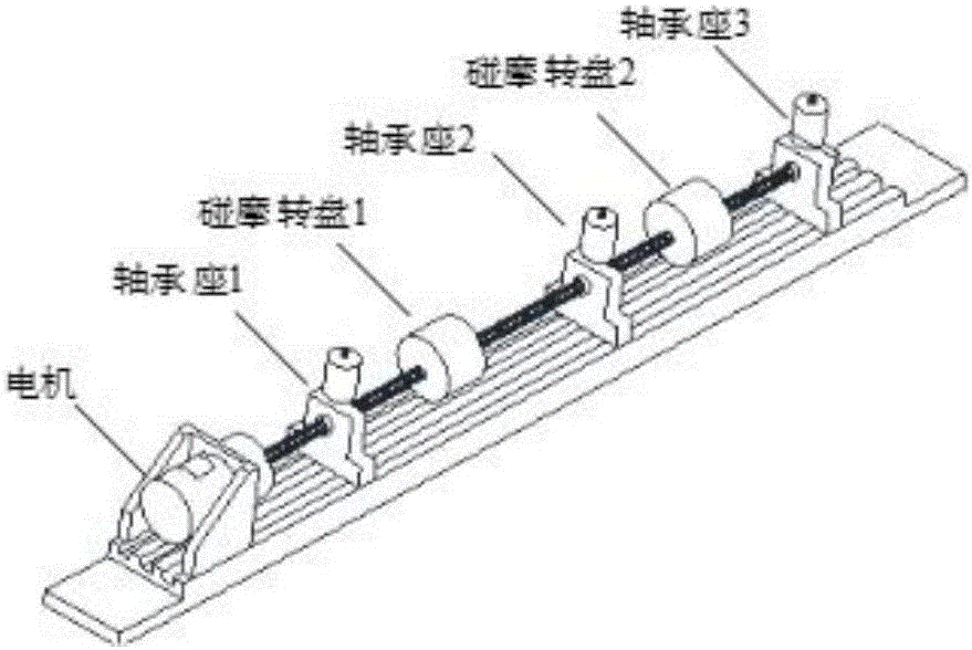
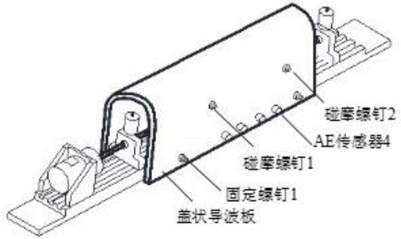
[0051] The experimental system adopted in the present invention is shown in Fig. 2, which is composed of a rotor rubbing test bench, a cover-shaped waveguide, a governor, and an acoustic emission acquisition system. The rotor rubbing test bench is composed of three bearing housings with sliding bearings to support the rotor, two rubbing discs and rubbing screws. The rubbing screw can point to the center of the rotating shaft through the screw hole on the cover-shaped waveguide plate, and is in contact with the side of the disc. There are four ...


PUM


Abstract

The invention discloses a rub-impact sound emission fault position identification method based on near field sound source focusing positioning. According to the method, sub-band decomposition of a sound emission signal acquired by a rub-impact sound emission test device is carried out to extract a characteristic signal; a subspace frequency focusing method is utilized to carry out frequency focusing of a sound emission characteristic signal, and decoherence processing on multiple coherent signals is carried out; lastly, a space spectrum estimation method is employed to carry out further precise sound source positioning. Through the method, fast fading, coherent and multi-modal problems of the broadband sound emission signal can be solved, so the rub-impact fault source position can be effectively identified. The method is advantaged in that the generation position of the rub-impact sound emission signal can be accurately identified, precision and complexity indexes are better compared with a positioning algorithm in the prior art, and the method is an effective rub-impact fault position detection method.

Description

technical field [0001] The invention belongs to the field of non-destructive testing, and relates to a positioning method for acoustic emission signals, in particular to a signal processing method for calculating the location of rubbing acoustic emission faults. Background technique [0002] Rubbing is a common nonlinear vibration fault of rotating machinery. Effective identification of rubbing parts is of great significance for diagnosing the cause of the fault and early warning of accidents. Compared with vibration signals, acoustic emission (AE) signals are sensitive to weak rubbing, and have unique advantages in rubbing detection. [0003] At present, the research of using acoustic emission sources to locate rubbing parts mainly focuses on time-of-flight positioning and spatial spectrum estimation theory. The time difference positioning method has achieved good positioning results in laboratory research. However, in actual operation, the calculated time difference is a...

Claims


Application Information

Patent Timeline
Patent Type & Authority Applications(China)
IPC IPC(8): G01M13/00
CPCG01M13/00
Inventor 邓艾东李晶赵力刘东瀛张瑞龙磊朱静
Owner SOUTHEAST UNIV
Why Eureka
Try Eureka