Ellipsoidal reflector perifocus high-precision positioning device and method

A technology of ellipsoidal reflector and positioning method, which is applied in the field of high-precision positioning devices near the focus of ellipsoidal reflector, which can solve the problems of large coma, astigmatism, and extremely high accuracy of assembly and adjustment.

Active Publication Date: 2017-04-26
HARBIN INST OF TECH
View PDF9 Cites 8 Cited by
  • Summary
  • Abstract
  • Description
  • Claims
  • Application Information

AI Technical Summary

Problems solved by technology

[0003] However, since the collection aperture angle of the ellipsoidal reflector is very large, it requires extremely high adjustment accuracy. When the point source and the far focus of the ellipsoidal reflector deviate slightly in the radial direction, it will cause large coma aberration and Astigmatism, therefore, in order to take advantage of the large numerical aperture and strong contrast of the ellipsoidal reflector, it is necessary to fine-tune the ellipsoidal reflector

Method used


Image

  • Ellipsoidal reflector perifocus high-precision positioning device and method

Examples


specific Embodiment 1

[0036] This embodiment is an embodiment of an ellipsoid reflector near-focus high-precision positioning device.

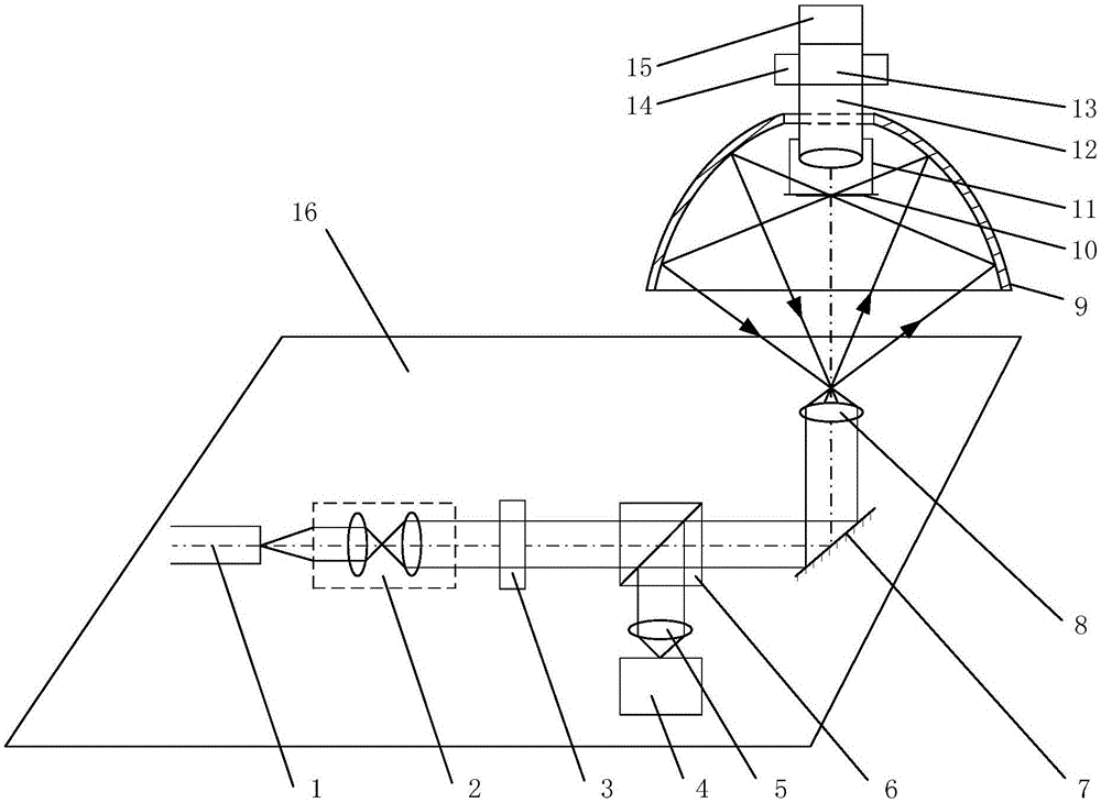
[0037] The high-precision positioning device near the focus of the ellipsoid mirror in this embodiment has a schematic structural diagram as figure 1 shown. The near-focus high-precision positioning device of the ellipsoid mirror includes a laser 1, a collimator beam expander 2, an attenuation plate 3, a far-focus CCD 4, a tube mirror 5, a beam splitter 6, a plane mirror 7, a far-focus focusing objective lens 8, an ellipsoid Spherical reflector 9, coating sample 10, connection table 11, near-focus focusing objective lens 12, piezoelectric ceramics 13, X-Y axis precision drive table 14, near-focus CCD15 and six-degree-of-freedom workbench 16;

[0038] Laser 1, collimator beam expander 2, attenuation plate 3, far-focus CCD 4, tube mirror 5, beam splitter 6, plane mirror 7 and far-focus focusing objective lens 8 form the lower optical path, which is set on the six-de...

specific Embodiment 2

[0041] This embodiment is an embodiment of a high-precision positioning method for the near focus of an ellipsoid mirror.

[0042] The high-precision positioning method for the near-focus of the ellipsoidal reflector in this embodiment is implemented on the high-precision positioning device for the near-focus of the ellipsoidal reflector described in Embodiment 1. The method includes the following steps:

[0043] Step a, performing the far focus positioning of the ellipsoidal reflector;

[0044] Step b. On the basis of step a, perform near-focus positioning of the ellipsoidal reflector.

specific Embodiment 3

[0046] This embodiment is an embodiment of a high-precision positioning method for the near focus of an ellipsoid mirror.

[0047] The high-precision positioning method of the near focus of the ellipsoid mirror of the present embodiment, on the basis of the specific embodiment 2, further defines that step a includes the following steps:

[0048] Step a1, turn on the laser 1, and use the attenuation sheet 3 to attenuate the intensity of the parallel light beam emitted from the collimator beam expander 2, so that the image sensor 4 can effectively image;

[0049] Step a2, constantly adjusting the six-degree-of-freedom workbench 10 to obtain the intensity information and roundness information of the light spot collected by the image sensor 4 under different degrees of freedom;

[0050] Step a3, combining the intensity information and roundness information of the light spot into an evaluation function, and establishing a degree of freedom-evaluation function table;

[0051] Step a4...


PUM


Abstract

The invention provides an ellipsoidal reflector perifocus high-precision positioning device and method, and belongs to the optical confocal microscopy technical field and optical precise measurement field. The device is formed by a lower light path for ellipsoidal reflector apofocus high-precision positioning and an upper light path for ellipsoidal reflector perifocus high-precision positioning. The method is characterized by, to begin with, carrying out ellipsoidal reflector apofocus positioning through the lower light path; and then, carrying out ellipsoidal reflector perifocus positioning through the upper light path. The device and method, to begin with, by making full utilization of the special feature of ellipsoidal reflector bifocus conjugation, provide a technological means for ellipsoidal reflector perifocus positioning, and then, realize ellipsoidal reflector perifocus high-precision positioning through an imaging technological means; and the device and method provide the technological means for a precise-adjustment ellipsoidal reflector to reduce coma and astigmatism of the ellipsoidal reflector, and play a promotion role in application and development in the optical confocal microscopy technical field and the optical precise measurement field.

Description

technical field [0001] The invention relates to a near-focus high-precision positioning device and method of an ellipsoid reflector, belonging to the field of optical confocal microscopy technology and the field of optical precision measurement. Background technique [0002] With the development of microscopic technology, reflective microscopic imaging system has been paid more and more attention. The structures that can realize imaging under large numerical aperture angle are: parabolic mirror, hyperbolic mirror and ellipsoidal mirror. Ideally, the ellipsoidal mirror has the advantages of large numerical aperture and strong contrast, and has broad application prospects and commercial value in the field of optical confocal microscopy and optical precision measurement. [0003] However, since the collection aperture angle of the ellipsoidal reflector is very large, it requires extremely high adjustment accuracy. When the point source and the far focus of the ellipsoidal refl...

Claims


Application Information

Patent Timeline
Patent Type & Authority Applications(China)
IPC IPC(8): G02B7/182
CPCG02B7/182
Inventor 李梦周刘俭李强谭久彬高姗
Owner HARBIN INST OF TECH
Why Eureka
Try Eureka