Fault injection method and fault injector of squirrel cage asynchronous motor rotor conducting bar

A technology of rotor guide bars and asynchronous motors, which is applied in the fields of instruments, electrical digital data processing, and special data processing applications, and can solve the problems of guide bar fault injection of asynchronous motors, etc.

Active Publication Date: 2017-04-26
CENT SOUTH UNIV
View PDF5 Cites 4 Cited by
  • Summary
  • Abstract
  • Description
  • Claims
  • Application Information

AI Technical Summary

Problems solved by technology

However, it has not been seen to use the idea of ​​multi-loop mathematical model theory to inject faults into t...

Method used


Image

  • Fault injection method and fault injector of squirrel cage asynchronous motor rotor conducting bar
  • Fault injection method and fault injector of squirrel cage asynchronous motor rotor conducting bar
  • Fault injection method and fault injector of squirrel cage asynchronous motor rotor conducting bar

Examples


Embodiment 1

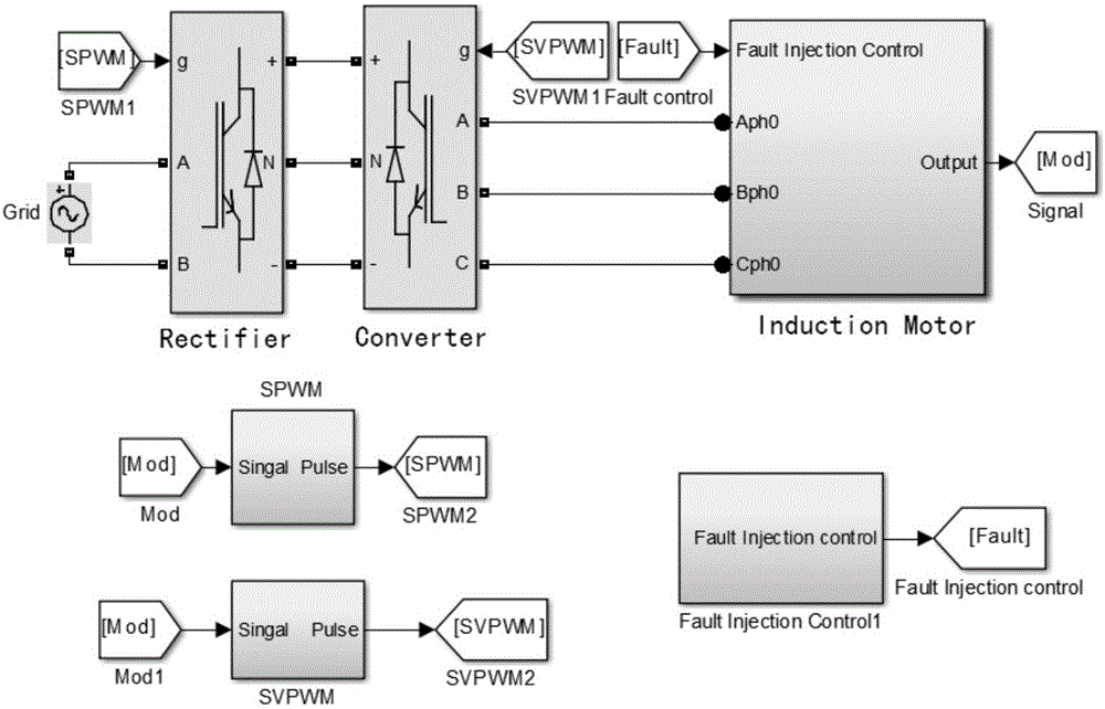
[0098] Specific embodiments of the present invention will be described below in conjunction with the accompanying drawings. The present embodiment is carried out under the virtual simulation platform Simulink software environment, as figure 2 As shown, the simulation platform includes power supply, rectifier, inverter, asynchronous motor, control circuit and fault injector. The rectifier is modulated by SPWM, and the inverter is controlled by a voltage space vector modulation (SVPWM) strategy. The left side of the three-level inverter provides a stable DC voltage for the two supporting capacitors, and the three-phase alternating current with adjustable frequency is output to the asynchronous motor through the three-level inverter. Some parameters of the asynchronous motor are shown in Table 1.

[0099] Table 1. Some experimental parameters of asynchronous motors

[0100]

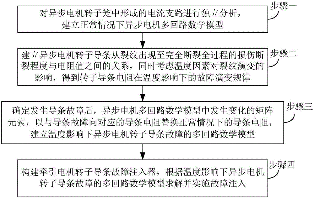
[0101] Such as figure 1 As shown, the rotor bar fault injection method of the squirrel-cage async...

Embodiment 2

[0177] Corresponding to the above method embodiments, this embodiment discloses a fault injector, such as Figure 6 And as shown in 7, it includes three parts: user setting, control realization and fault model library.

[0178] The user setting is used to receive the failure time and failure parameters set by the user.

[0179] The control realization includes fault injection controller, temperature module, real-time model parameter calculation module and model switching module; among them, the fault injection controller interacts with the user setting module to send out control signals to determine the fault mode and fault parameters to be injected, etc.; the temperature The module is used to simulate two types of temperature sources and output temperature signals; the real-time model parameter calculation module is based on the control signal sent by the fault injection controller and the temperature signal sent by the temperature module, and calculates the changes in the mu...


PUM


Abstract

The invention relates to the technical field of motors, and discloses a fault injection method and a fault injector of a squirrel cage asynchronous motor rotor conducting bar, so as to simulate the performance degradation rule of the conducting bar in an entire crack evolution stage under the influence of temperature and provide a real and reliable simulation environment for asynchronous motor conducting bar faults. The method provided by the invention comprises the following steps: establishing a relationship between a damage rupture degree of the asynchronous motor conducting bar in a whole process from the occurrence of cracks to complete rupture and a resistance value, and meanwhile considering the influence of a temperature factor to the crack evolution to obtain a fault evolution rule of the rotor conducting bar resistance under the influence of temperature; and after the conducting bar fault is determined, replacing the conducting bar resistance corresponding to the conducting bar fault with the conducting bar resistance under normal conditions according to the varying matrix elements in an asynchronous motor multiloop mathematic model, and establishing the multiloop mathematic model of the asynchronous motor rotor conducting bar faults under the influence of the temperature for solving and implementing fault injection.

Description

technical field [0001] The invention relates to the technical field of electric motors, in particular to a method for injecting a fault into a rotor bar of a squirrel-cage asynchronous motor and a fault injector. Background technique [0002] The asynchronous motor is an important part of the traction drive system, and its abnormal operation will affect the stable operation of the system. Due to the excessive mechanical stress and thermal stress on the rotor guide bar during starting and braking, as well as the defects in the manufacturing process of the rotor itself, it is prone to failures such as fracture. Statistics show that rotor bar failures account for about 10% of motor failures. [0003] When an asynchronous motor has a rotor bar failure, the continuous operation will cause a larger current to flow through the adjacent bars and withstand greater thermal and mechanical stress, resulting in more bar breaks and aggravating vibration and noise. and current fluctuatio...

Claims


Application Information

Patent Timeline
IPC IPC(8): G06F17/50
CPCG06F30/20
Inventor 彭涛赵帅阳春华史露杨超尹进田杨笑悦贺泽洲刘博陶宏伟李晟
Owner CENT SOUTH UNIV
Why Eureka
Try Eureka