Frictional nano-generator for collecting vibration energy and vibration sensor
A nano-generator and vibration energy technology, applied in friction generators, instruments, measuring devices, etc., can solve problems such as high threshold output power, increase system volume and quality, unfavorable system integration applications, etc., and achieve excellent output electrical performance Effect
- Summary
- Abstract
- Description
- Claims
- Application Information
AI Technical Summary
Problems solved by technology
Method used
Image
Examples
Embodiment 1
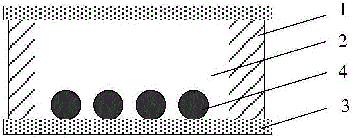
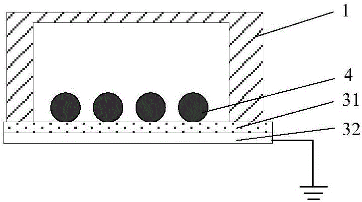
[0043] The friction nano generator for collecting vibration energy provided by this embodiment, for its typical structure, see figure 1 with figure 2 , Including a supporting member 1, a vibrating power generation membrane 3 and several power generating units 4, wherein the supporting member 1 is provided with a cavity 2; the vibrating power generation membrane 3 is provided at the opening of the cavity 2, and the vibrating power generation membrane 3 includes an electrode layer. The electrode layer is electrically connected to the ground; a number of power generation units 4 are arranged in the cavity 2; under the action of vibration, the vibrating power generation film 3 vibrates, and the power generation unit 4 collides with the vibration power generation film 3, and charges are induced in the electrode layer. A current is formed between the electrode layer and the ground, which can provide power to the load or serve as a vibration sensing signal.
[0044] In this embodiment, ...
Embodiment 2
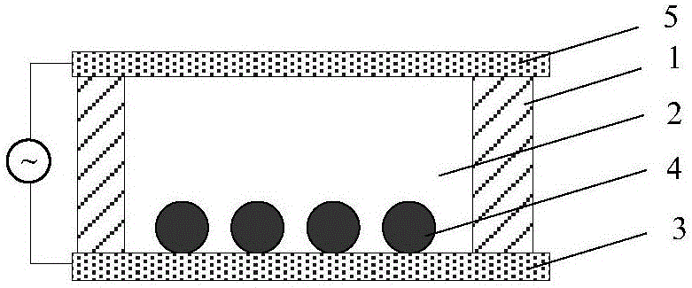
[0065] The friction nano generator for collecting vibration energy provided by this embodiment, for its typical structure, see image 3 , Including a support member 1, two vibration power generation membranes 3 and 5, and several power generation units 4, wherein the support member 1 is provided with a cavity 2, which is a through hole including two upper and lower openings; the vibration power generation membrane 3 and 5 are respectively arranged at the upper and lower openings, the vibrating power generation membranes 3 and 5 both include electrode layers, and the electrode layers of the two vibrating power generation membranes 3 and 5 are electrically connected to each other; a number of power generation units 4 are set in the cavity 2; Under the action of vibration, the vibration generating film 3 and / or 5 vibrates, and the generating unit 4 collides with the vibration generating film 3 and / or 5. Under the action of electrostatic induction, a current is formed between the two...
Embodiment 3
[0073] For the typical structure of the friction nanogenerator for collecting vibration energy of this embodiment, see Figure 5 with Image 6 , Including a supporting member 1, a vibrating power generation membrane 3 and a number of power generation units 4. The only difference from the first and second embodiments is that the supporting member 1 includes a plurality of cavities 2.
[0074] Image 6 It is a three-dimensional schematic diagram of a typical structure of the power generation unit 4 in the cavity of the supporting member 1.
[0075] A plurality of cavities 2 may be distributed in an array in the supporting member. Preferably, the plurality of cavities are cylindrical through holes, especially cylindrical through holes, and the height of each cavity may range from 0.1 cm to 100 cm. The diameter of each cavity is 4mm-20cm.
[0076] Generally, the voltage of the friction nanogenerator is higher and the current is lower. The structure of this embodiment connects multiple g...
PUM
| Property | Measurement | Unit |
|---|---|---|
| Particle size | aaaaa | aaaaa |
| Size | aaaaa | aaaaa |
Abstract
Description
Claims
Application Information
 - R&D
- Intellectual Property
- Life Sciences
- Materials
- Tech Scout
- Unparalleled Data Quality
- Higher Quality Content
- 60% Fewer Hallucinations
Browse by: Latest US Patents, China's latest patents, Technical Efficacy Thesaurus, Application Domain, Technology Topic, Popular Technical Reports.
© 2025 PatSnap. All rights reserved.Legal|Privacy policy|Modern Slavery Act Transparency Statement|Sitemap|About US| Contact US: help@patsnap.com


