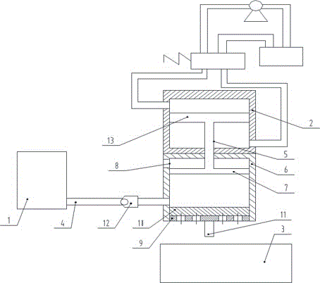
Device for filtering cutting fluid of grinding lathe
A technology of filtering device and cutting fluid, applied in the direction of filtration and separation, membrane filter, fixed filter element filter, etc., to achieve the effect of shortening filtration time, reducing time cost and low manufacturing cost
- Summary
- Abstract
- Description
- Claims
- Application Information
AI Technical Summary
Problems solved by technology
Method used
Image
Examples
Embodiment 1
[0019] like figure 1 As shown, the present invention is used for the device of filtering cutting fluid of grinding lathe, comprises storage tank 1, hydraulic cylinder 2, filtering device, liquid storage tank 3 and pipeline 4; Said storage tank 1 is used for storing cutting fluid, and said pipeline 4 Connect the storage tank 1 with the filter device; the cutting fluid enters the filter device through the pipeline 4. The liquid storage tank 3 is located below the filter device, and the liquid storage tank 3 is used to store the liquid filtered by the filter device; the filter device includes a filter assembly and a filter cylinder 6 with a bottom opening, and the filter assembly is arranged on the filter cylinder 6 The bottom; hydraulic cylinder 2 includes cylinder, piston rod 5 and piston I13. The free end of the piston rod 5 of the hydraulic cylinder 2 passes through the top of the filter cylinder 6 and is positioned in the inner chamber of the filter cylinder 6; a piston 7 i...
Embodiment 2
[0025] The structure of this embodiment is the same as that of Embodiment 1, and this embodiment is an instruction for the use of Embodiment 1.
[0026] Use the steps of the present invention as follows:
[0027] 1. Supply oil to the lower chamber of the hydraulic cylinder 2, the piston I13 in the hydraulic cylinder 2 moves upward under the push of the oil pressure, and drives the piston 7 connected to the piston rod 5 to move upward, and the volume of the inner cavity at the lower end of the piston 7 increases Large, forming a local cavity; at this time, the one-way valve 12 is opened, and the cutting fluid is sucked from the storage tank through the pipeline 4;
[0028] 2. Supply oil to the upper cavity of the hydraulic cylinder 2, the piston I13 in the hydraulic cylinder 2 moves downward under the push of the oil pressure, and drives the piston 7 connected to the piston rod 5 to move downward, and the inner cavity at the lower end of the piston 7 The volume is reduced, and...
PUM
 Abstract
Description
Claims
Application Information
 - R&D
- Intellectual Property
- Life Sciences
- Materials
- Tech Scout
- Unparalleled Data Quality
- Higher Quality Content
- 60% Fewer Hallucinations
Browse by: Latest US Patents, China's latest patents, Technical Efficacy Thesaurus, Application Domain, Technology Topic, Popular Technical Reports.
© 2025 PatSnap. All rights reserved.Legal|Privacy policy|Modern Slavery Act Transparency Statement|Sitemap|About US| Contact US: help@patsnap.com

